


RV Engine Bay LED Light Kit
For diesel pusher motorhomes, adding engine bay LED lighting is becoming more popular these days. Doing so not only adds a pleasant glow from within the engine bay itself, it can provide on-demand functional lighting if you need to inspect the engine bay area for whatever reason. While engine bay LED lighting is usually installed along with a full perimeter under-glow light system under the entire RV, it's not always the case. Engine bay lighting can also be installed stand alone; totally your choice.
Be sure to scroll down into this product page for important details including FAQs, configuration specifics, product options, specifications, installation docs and more.
READ THIS BEFORE ORDERING!
Successful installation requires reading the written installation directions. While our How-To Videos offer helpful overviews, they do not replace the detailed documentation. Reading the instructions carefully is essential for proper fit, function, and long-term performance. Most support calls and warranty claims we receive stem from customers who don't read this information. Please take our advice and read the directions. We promise, you'll be happy with the results if you do.
PRODUCT HIGHLIGHTS
This RV Engine Bay LED Light kit can be configured with one, two, three or four different LED strips to fit just about any RV diesel pusher engine bay configuration. The lengths of these LED strips range from 12" to 60". Each LED strip has a 10' power lead hard wired to one end of the strip. They're available in eight single color options and three multi-color options: RGB, RGBW and RGBA (details about these are in this product description). The kit can be configured as a stand alone light kit with it's own controller or switch so the engine bay lights can be operated on their own. Or, it can be configured to integrate with an existing Boogey Lights® LED light kit such as our full-perimeter Under-Glow light kit as seen in many of the product photos on this page. In the majority of cases, the engine bay LED light kit is connected to and controlled by the RV under-glow light kit with a separate cut off toggle switch to disable the Engine Bay Light kit for situations where you want the under-glow system to be on but the engine bay lighting to be off.
INSTALL CONSIDERATIONS
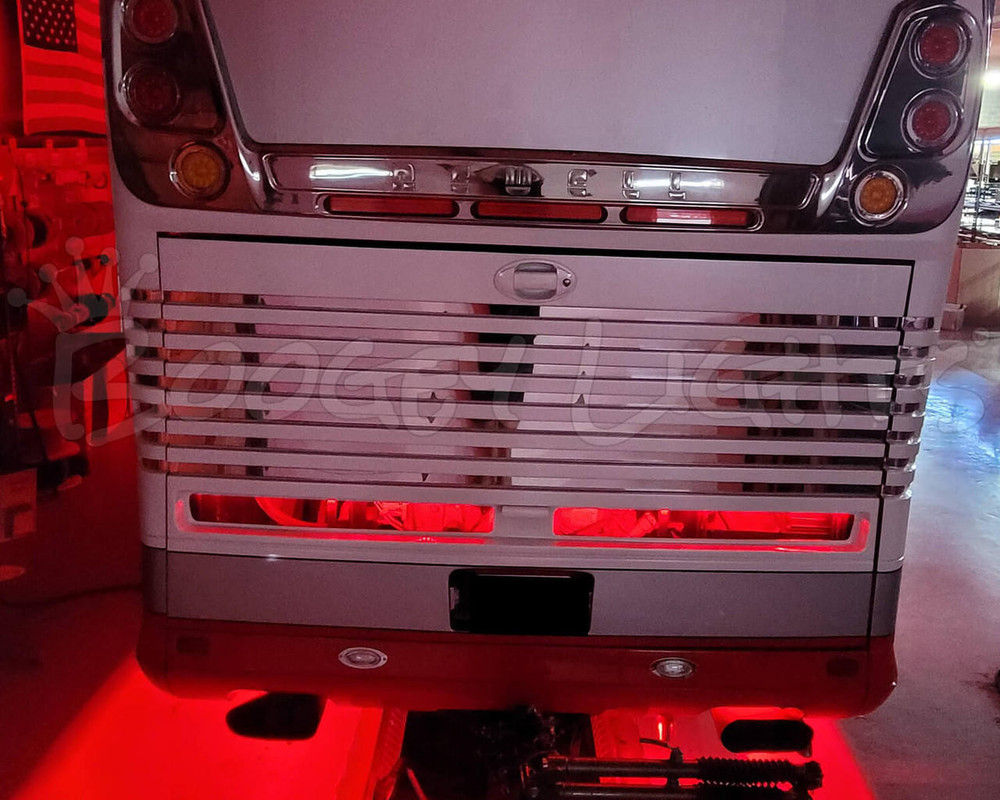
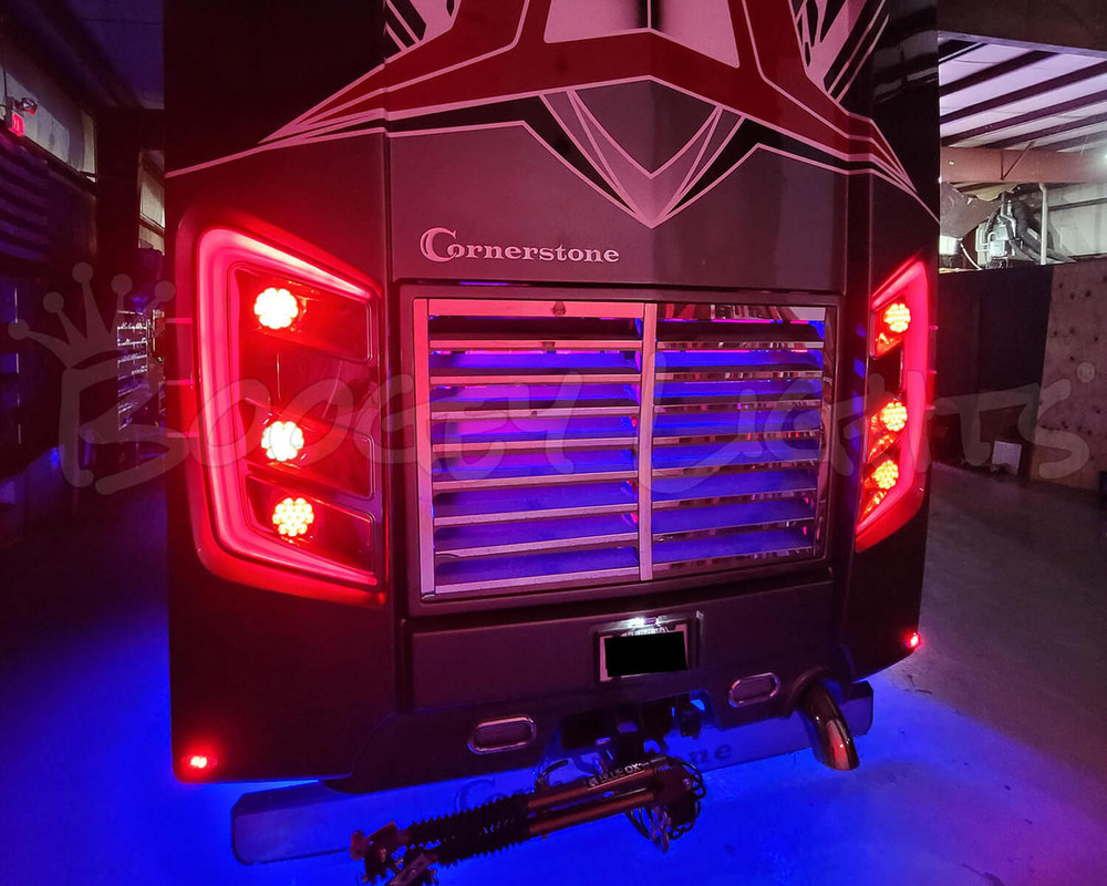
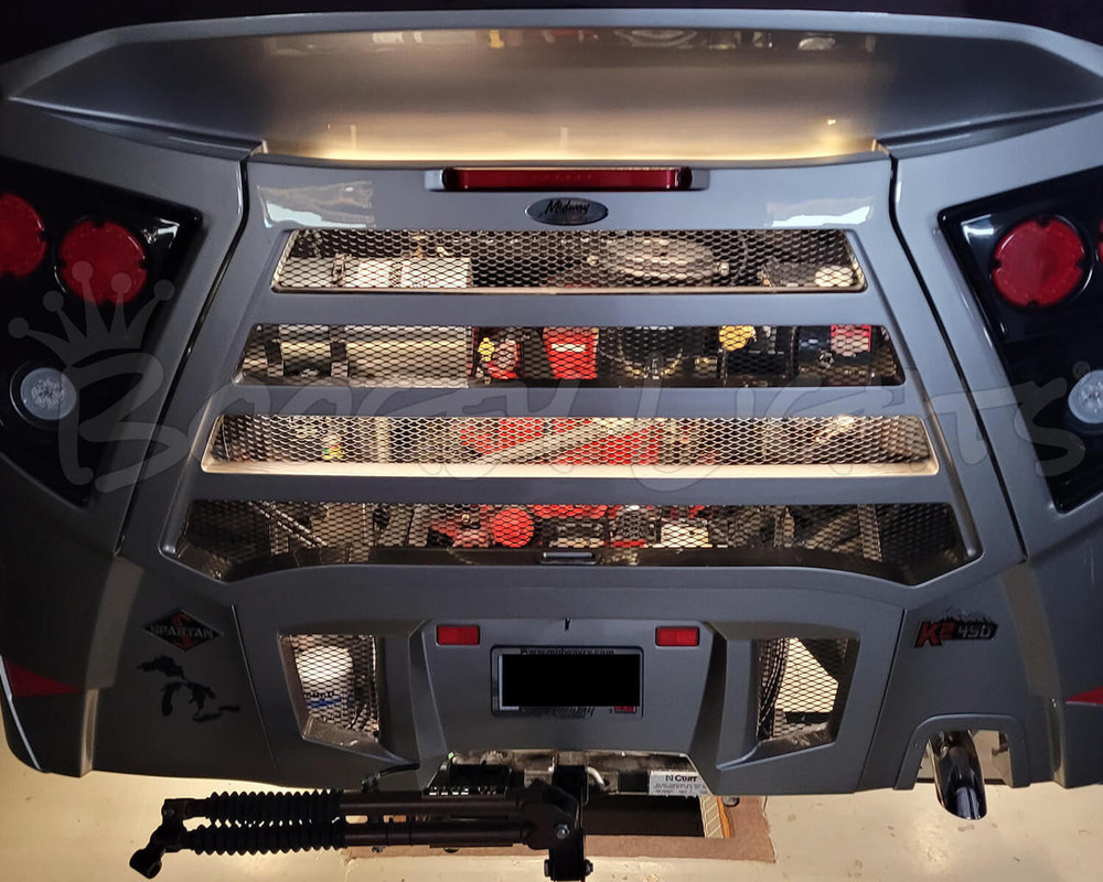
When it comes to diesel pusher engine bay lighting, there is no one size fits all solution. Too many variables. The goal of engine bay lighting is to mount the LED strip(s) in a place where the glow from those light strips shine through the bay door structure without being able to see the actual LED light strips from outside the engine bay. This means the structure of the engine bay door largely determines where the LED strip(s) will need to be mounted and how many LED strips are needed to provide the glow you want. Some engine bay doors have large slots making it easier. Others have smaller slots and/or screens which require more carefully placed LED strips. For example, we've had to install the LED strip directly to the bay door in some cases in order to get the best glow effect.
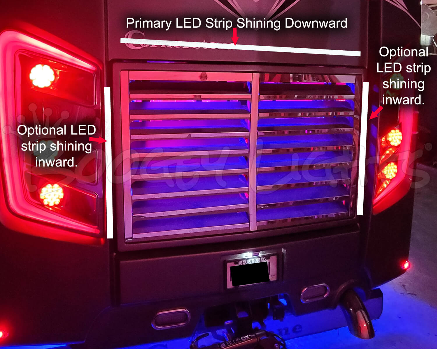
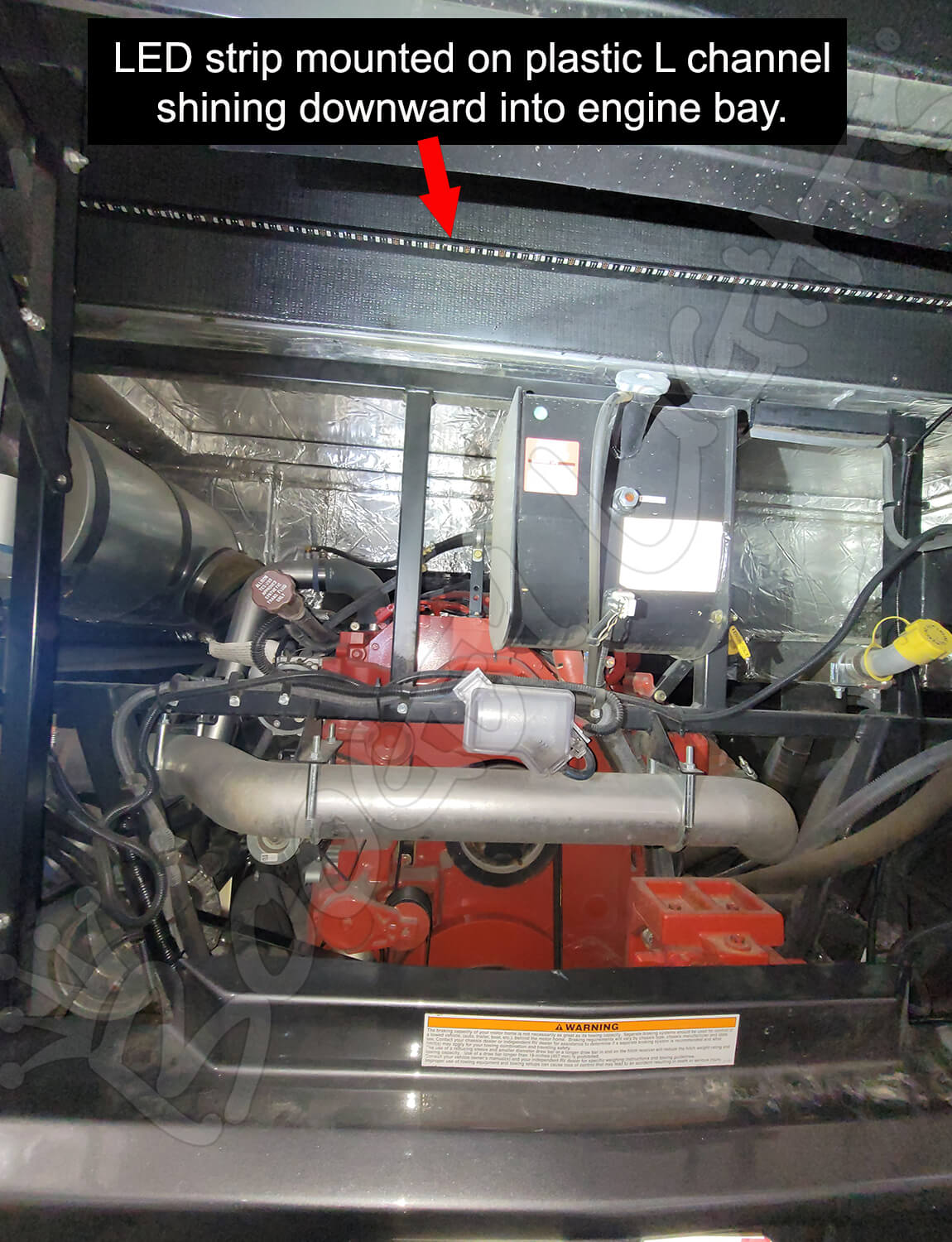
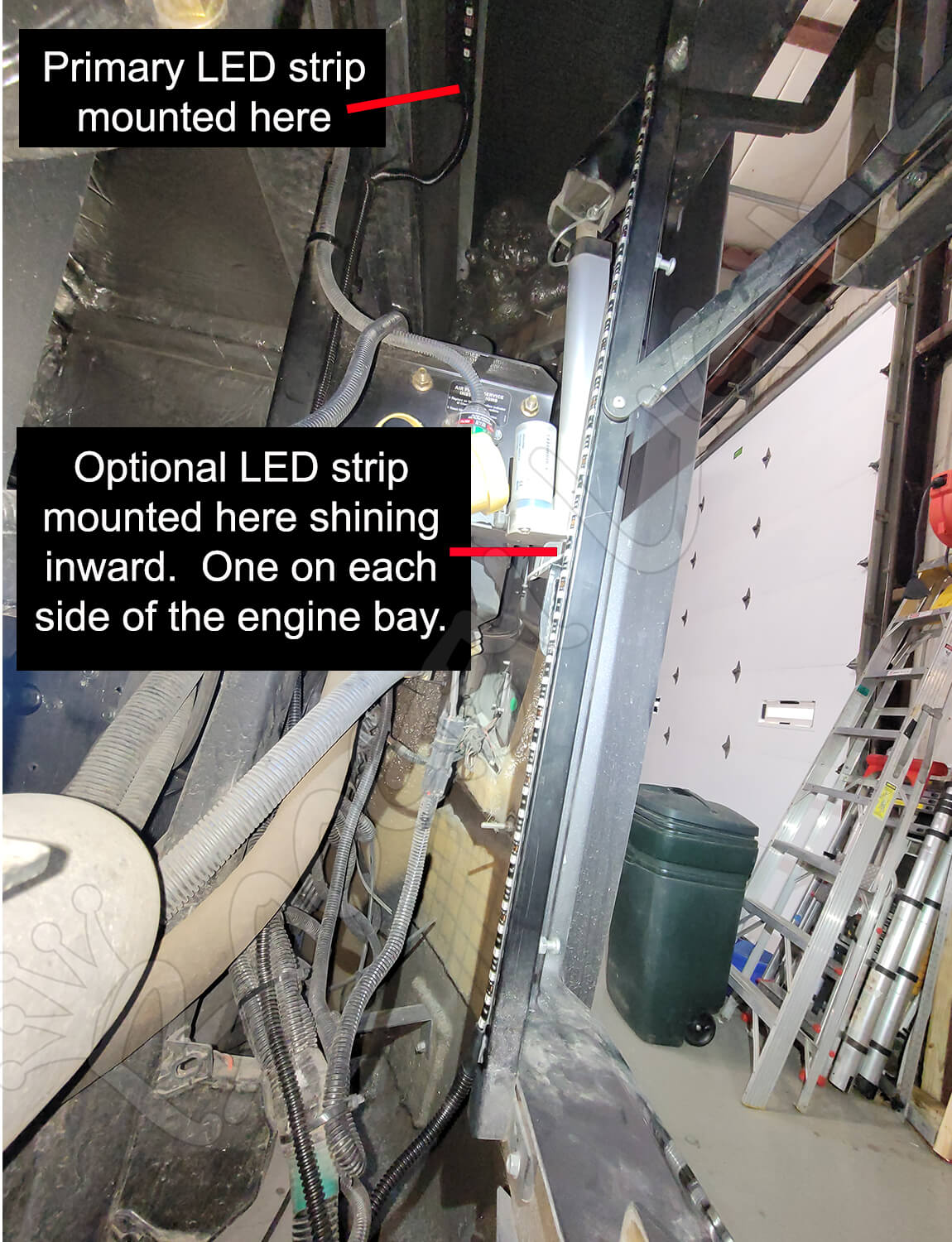
Before ordering, you'll need to examine your engine bay area and in particular, the bay door structure. Most engine bay lighting systems will have the primary (and longest) LED strip mounted at the top of the engine bay with the LED strip shining downward illuminating the engine bay. We do this using some plastid L channel that is usually riveted to the back wall of the engine bay a few inches above the hinge point of the engine bay door. See photos below. On some engine bays it's possible to mount two vertical LED strips on each side of the bay both of them shining inward toward the center. An example of that type of installation is shown in the photo below. In other installations you may have to mount at least one led strip on the bay door itself to achieve the lighting glow you're looking for. Each bay is a little different. This light kit can be configured with up to four LED strips (only one is required -- the other three are optional). We've never seen an engine bay that required more than four LEDs strips. Once you've decided where you want to mount the LED strip(s), take measurements of the areas. Make sure the area is smooth and flat. Those measurements are used in the product configuration for each LED strip.
AVAILABLE OPTIONS
LED Strip Length: This is the primary LED strip which is usually installed horizontally across the top of the engine bay opening shining downward (see photo in the above section). This strip is usually mounted to plastic L channel (details about this are further on in this product description). Each LED strip has 10' power lead hard wired to one end of the strip. Select the length of the primary LED strip. The default is 48" which is a common length for engine bay openings. You can however adjust the length based on your measurements. The strip can can be cut every 3 LEDs if so desired.
LED Strip Length 2: Optional. Select the length of LED strip number two if desired. The default is NONE. You can however adjust the length to fit your installation. 10' power lead hard wired to one end of the strip.
LED Strip Length 3: Optional. Select the length of LED strip number three if desired. The default is NONE. You can however adjust the length to fit your installation. 10' power lead hard wired to one end of the strip.
LED Strip Length 4: Optional. Select the length of LED strip number four if desired. The default is NONE. You can however adjust the length to fit your installation. 10' power lead hard wired to one end of the strip.
Color Configuration: Select the LED color configuration you want from the drop down box. Single Color, Multi-Color RGB or Multi-Color RGBx. See CONFIG tab for more detail on the multi-color options. Your color configuration choice here will determine the next two options presented: LED Color Option and Kit Configuration Option.
Kit Configuration: Select the type of switch/controller combination you want from the drop down. These options are specific to the LED Color Configuration you select. See the CONFIG and CONTROLLER tabs for more details on these options.
Add L Channel for Mounting: If YES, we will include black plastic L channel 2" longer than the length of your primary LED strip. This plastic L channel will be used to mount the primary LED strip above the engine bay area as shown in the photos in the previous section. The default is set to YES because the vast majority of installations will require this L channel to mount that primary LED strip. If however you don't need the plastic L channel, you can select NO and save a little money. Make your selection from the drop down box.
Add Cut Off Toggle Switch: For multi-color (RGB or RGBx) installations, if you're connecting this engine bay light kit to an existing Boogey Lights® lighting installation (e.g. full-perimeter under-glow light system), we offer the option of adding a Cut-Off Toggle Switch to the kit. This cut off switch gives you the ability to turn off just the Engine Bay lights while leaving the rest of your Boogey Lights® lighting system on. This toggle switch is installed on the ground wire that feeds the LEDs mounted in the engine bay. We typically will mount the toggle switch just inside the engine bay door making it easy to turn turn it on/off.
Color Options and Considerations
This Engine Bay LED Light Kit is offered in eight single color options and in the following multi-color configurations: RGB, RGBW (RGB + warm white) and RGBA (RGB + amber).
For the majority of Engine Bay lighting systems, the engine bay lights are an add-on to an existing Boogey Lights lighting system such as a full-perimeter under-glow system. In those cases the switching or control mechanism will be the existing lighting system. If that is what you're doing, you won't be making a switch or controller selection. Simply select the option indicating you're connecting the engine bay lights to an existing Boogey Lights system. If however your engine bacy lighting system is a stand alone sysetm, you'll need to make a switch or controller selection. If installing single color LEDs you'll need a switch of some kind. We offer a couple of wireless options. For multi-color installations, we offer a number of LED controller options depending on the type of RGB led strip you buy. You'll find a more detailed discussion on these options under the CONFIG and CONTROLLER tabs on this product page. Note that the switching and controller options offered will change based on your COLOR CONFIGURATION choice.
For the RGB options, we offer both a 4 button Key Fob or 15 button G2 M7 style wireless RF remote. For the RGBx options, we offer a 15 button G2 M7 style wirless RF remote. All of these controller options are our latest GEN2 COMBO RF + Bluetooth LED Controllers. Note that these controller options are based on LED capacity. See the CONFIG and CONTROLLER tabs on this product page for signficantly more detail on these RGB and RGBx LED Controller options. You'll also find a photo comparison in the product carousel.
These RGB/RGBx LED controllers also allow you to use your Bluetooth enabled smartphone and our free IOS/Android APP to operate the lights. With the included RF remote you can change between 7 pre-set colors (Red, Green, Blue, White / 6000k, Light Blue, Lime Green/Yellow, Hot Pink/Purple) and functions of on/off, dimming (7 levels), strobing/flashing, breathing and blending. You can also use your Bluetooth enabled smart phone to create a custom look. The Bluetooth APP allows you to program the RGB diodes of any of our RGB, RGBW and RGBA LED strips with over 16 million different color combinations plus three pre-sets. Also, the Bluetooth APP offers 2 and 3 color rotation programming. Click the APP navigation tab on this product page for significantly more information on both the Bluetooth capabilities and APP functionality (including a video showing how the Bluetooth APP works).
What is RGBW? On the RGBW led strip, in addition to RGB, you get one extra diode which is Warm White. That warm white diode has a Kelvin temperature of 2400 which means it has a yellowish look giving it a warmer, softer, candle like look (see photo below). That fourth diode on the RGBW led strip is often wired to an existing OEM switch allowing you to turn on just the warm white diode with the flip of a switch. Other options include adding a dimmer switch or even another LED controller just to operate that fourth warm white diode. See the CONFIG tab on this product page for more details on this option.
What is RGBA? On the RGBA led strip, in addition to RGB, you get one extra diode which is AMBER. That fourth diode on the RGBA led strip is often wired to an existing OEM switch allowing you to turn on just the AMBER diode with the flip of a switch. Other options include adding a dimmer switch or even another LED controller just to operate that fourth warm white diode. See the CONFIG tab on this product page for more details on this option.
VIDEO: Installing Engine Bay Lights
This is a quick video showing an engine bay light kit installation.
OTHER ITEMS YOU MAY NEED
No two installation scenarios are the same. Not everyone shares the same installation quality goals. Some folks are OK with twisting wires together, others want to solder them. Some folks are OK with running wires where they may be seen or unprotected to save money/time, others want a tidy, clean install without any wires showing. Some folks are OK with mounting their LED strips to whatever surface they can find, others want to take the time necessary to build out appropriate mounting surfaces to provide the best lighting effect on their vehicle. The point is it's not possible to provide all the materials necessary for all installation scenarios and quality goals. Our light kits provide the essential components needed for a high-quality, functioning lighting system. Installation of our light kit to your specific vehicle may however require additional items to make it look and fit the way you want. This is particularly the case with electrical wiring and mounting of LED strips. Before proceeding with your installation we suggest you consider THESE OTHER ITEMS.
RETURN POLICY EXCEPTION
Make sure you take your measurements carefully. This product is considered a custom ordered product. It cannot be returned without a restocking fee applied or returned for store credit only. Be sure to read our RETURN POLICY for details.
NOTE ON EXTENDED USE
The LEDs used in this product are very bright; the brightest 12vdc LED lights available. They're designed to be used for accent lighting applications where they are typically powered on for a few hours (usually on a dimmed setting) and then powered off. While they can be used in functional lighting applications (e.g. bright white to temporarily illuminate a work area), the lights should NOT be left powered on for extended periods of time (e.g. 6+ hours). If the LEDs are left powered on for long periods of time - particularly on their brightest setting - the LEDs closest to the power source will have a burned look to them over time. This is because the amount of voltage being pulled through the LEDs closest to the power source will be higher than the voltage going through the LEDs further down the strip. The end result is that those LEDs closest to the power source will be hotter thus creating the burned look. This will occur mostly when displaying the color white on a full brightness setting but can also occur with other colors. For this reason, we do NOT suggest leaving these LED lights powered up for extended periods of time particularly on their brightest setting. Burned looking LEDs is NOT covered under warranty.
Will Boogey Lights® Work with Other Brands?
The short answer is probably not. All Boogey Lights® RGB LED strips are COMMON CATHODE LEDS. They share a common ground and will only work with positively switched controllers. Most LED strips on the market today are COMMON ANODE because the controller technology used to power them is less expensive to manufacture. However they're not nearly as bright and are an overall inferior design when compared with COMMON CATHODE LEDs. For more information, click the button below.
WHY BOOGEY LIGHTS®?
Unlike most every other light kit out there, these light kits are ACCENT LIGHT KITS. When mounted properly, you'll never see the LED lights themselves. You'll only see the glow from the LEDs. If you're interested in learning more about WHY Boogey Lights are different than any other LED lighting system on the market, click here: WHY BOOGEY LIGHTS . We do a deep dive into the ten differences between Boogey Lights® and all the others.
A Word About 12vdc Power
All Boogey Lights® controllers and LED strips operate on 12vdc which is readily available on any RV made and offered for sale in North America. An essential skill with installation of any Boogey Lights LED products is knowing how to correctly wire the product to a 12vdc circuit. This includes understanding the importance of having a properly sized fuse at the power source, polarity, how to properly seal an electrical connection, using properly sized wire gauge for the load, measuring voltage and measuring the additional amperage draw you're adding. Be mindful of the amount of amperage you're drawing through your lighting circuit and to not exceed the circuit component limitations. The amount of power (amps) you're pulling through the circuit will vary based on a combination of three factors: 1) The number of LEDs in the circuit, 2) the amount of copper wire in the circuit and 3) the input voltage to the circuit. The amperage ratings for our switches, controllers and LEDs assume 12.5 vdc input or less. If you are uncertain or unfamiliar with any of these concepts, we urge you to ask someone who has the knowledge to assist you. Electricity is unforgiving.
THE KELVIN SCALE

Have a question you can't find the answer to here? Check out our FAQ's of the most commonly asked questions.
PRODUCT CONFIGURATION OPTIONS
The information on this page provides more detail about the product options you can select for this product. Simply click on each text box to expand the section about the topic.
LED STRIP LENGTH OPTIONS
This RV Engine Bay LED Light kit can be configured with one, two, three or four different LED strips to fit just about any RV diesel pusher engine bay configuration. The lengths of these LED strips range from 12" to 60". Each LED strip has a 10' power lead hard wired to one end of the strip. The default is 48" which is a common length for engine bay openings. You can however adjust the length based on your measurements. The strip can can be cut every 3 LEDs if so desired. At least one LED strip has to be ordered. The remaining three are optional. If you don't need the optional LED strips, leave the default setting at NONE.
The default length is 48" which is a common length for many slide outs. For shorter or longer lengths, use the KIT CONFIGURATION drop down box which offers these lengths: 16' 14', 12', 10', 8', 6', 4', 24' (2 - 12'), 20' (2 - 10') and 18' (1-10', 1-8'). Regardless of the length, each led strip includes a 15' power lead hard wired to one end of the LED strip. There are no connectors. Single color LED strips have 2 conductor power lead. RGB has 4 conductor power leads. RGBW and RGA both have 6 conductor power lead although on the RGBW, only 5 of the 6 leads are used. Single Color and RGB led strips are 3/8" wide (10mm). RGBW and RGBA are 1/2" wide (12mm). All are 1/8" high/thick.
COLOR CONFIGURATION
This product can be purchased in three color configurations: SINGLE COLOR, MULTI-COLOR RGB and MULTI-COLOR RGBx where 'x' is a variable for either warm white (RGBW) or amber (RGBA). The selection you make here will determine additional options presented.
Single color simply means the LED strip is one color all the time. The color cannot be changed. The color you choose is the color you get.
RGB Multi-Color means you can change or select different colors. All of the multi-color RGB options require an LED controller to operate. The advantage of RGB over a single color LED strip is that RGB gives you the ability to change colors as well as access other features such as dimming, flashing, breathing and color blending. With the bluetooth interface, you can save favorite color/feature sets as well as program 2 or 3 color rotation sequences. More detail about these advanced features can be found on this product page. With RGB you can choose between 7 colors using the hand held wireless remote (Red, Green, Blue, White / 6000k, Light Blue, Lime Green/Yellow, Hot Pink/Purple) and 16 million (using the bluetooth APP) different color combinations.
RGBx Multi-Color offers the same features as RGB with the addition of a fourth diode. We offer two RGBx options: RGBW and RGBA. RGBW is by far the most popular for RVs. RGBW includes all of the RGB colors and capabilities plus the addition of a warm white diode (2400 kelvin temp). Warm white is often referred to as a 'candle white' or 'soft white'. RGBA includes all of the RGB colors and capabilities plus the addition of an amber diode. Amber attracts fewer bugs than white. It's also not nearly as bright; easier on the eye at night which some folks prefer.
LED COLOR OPTIONS
The LED color options presented here will vary based on what your COLOR CONFIGURATION selection is in the previous step. Here's are the available options for all color configurations:
SINGLE COLOR
- Red
- Green
- Blue
- White (6000k, aka 'cool white')
- Orange
- Amber
- Pink
- Magenta (Hot Purple)
MULTI-COLOR RGB
- RGB
MULTI-COLOR RGBx
- RGBW (RGB + White)
- RGBA (RGB + Amber)
Single color simply means the LED strip is one color all the time. The color cannot be changed. The color you choose is the color you get. Multi-color means you can change or select different colors. All of the multi-color RGB options require an LED controller to operate. The advantage of RGB over a single color LED strip is that RGB gives you the ability to change colors as well as access other features such as dimming, flashing, breathing and color blending. With the bluetooth interface, you can save favorite color/feature sets as well as program 2 or 3 color rotation sequences. More detail about these advanced features can be found on this product page. With RGB you can choose between 7 colors using the hand held wireless remote (Red, Green, Blue, White / 6000k, Light Blue, Lime Green/Yellow, Hot Pink/Purple) and 16 million (using the bluetooth APP) different color combinations. RGBW includes all of the RGB colors and capabilities plus the addition of a warm white diode (2400 kelvin temp). Warm white is often referred to as a 'candle white' or 'soft white'. RGBA includes all of the RGB colors and capabilities plus the addition of an amber diode. Amber attracts fewer bugs than white. It's also not nearly as bright; easier on the eye at night which some folks prefer. Make your selection from the LED COLOR OPTION drop down. Click on the KELVIN SCALE button below for more information on the difference in color temperature.
KIT CONFIGURATION
The configuration options are the switching and/or controller selections you want for your light kit. The KIT CONFIGURATION options presented will vary based on your COLOR CONFIGURATION selection (SINGLE COLOR, MULTI-COLOR RGB and MULTI-COLOR RGBx).
For the majority of Engine Bay lighting systems, the engine bay lights are an add-on to an existing Boogey Lights lighting system such as a full-perimeter under-glow system. In those cases the switching or control mechanism will be the existing lighting system. If that is what you're doing, you won't be making a switch or controller selection. Simply select the option indicating you're connecting the engine bay lights to an existing Boogey Lights system. If however your engine bacy lighting system is a stand alone sysetm, you'll need to make a switch or controller selection. Here is an overview of each.
SINGLE COLOR KIT CONFIG OPTIONS
If you're purchasing a single color LED strip, at minimum you'll need a way to turn it on and off. Some customers may want the ability to dim the lights too. We offer the following switching and control options for those who are interested in purchasing a Single Color LED strip.
- No switches (provide your own). Select this option if you already have a means by which to switch the light on/off. Just be aware of the circuit capabilities of your existing switch. As a point of reference, a single 16' long LED strip with 300 LEDs will pull about 3.3 amps on full brightness white. Other colors will pull less amperage. Amperage data is available for all LED products on the SPECS tab.
- RF Wireless ON/OFF only (5 amps). Select this option if you want a simple wireless ON/OFF remote control (Key Fob style) to turn the lights on and off (no dimming or brightness control). Max amperage is 5 amps. If your installation is greater than 5amps, be sure to add a relay. As a point of reference, a single 16' long LED strip with 300 LEDs will pull about 3.3amps on full brightness white. Other colors will pull less amperage. Amperage data is available for all LED products on the SPECS tab
- RF Wireless ON/OFF/DIMMING control (10 amps). Select this option if you want a wireless remote control (M7 style) to operate the led strip. The wireless remote has a hand held control that allows you to turn the lights on, off and dim. In addition, you can strobe and breath the lights too. Bluetooth control is included as well. This controller is rated at a maximum amperage of 10 amps. Because it offers dimming capabilities, you cannot use a relay so 10 amps is the hard limit.
RGB MULTI-COLOR KIT CONFIG OPTIONS
All of the RGB controllers offered are our latest Generation 2 (aka GEN2 or G2) LED Controllers. They are combo controller meaning they offer both RF and Bluetooth control. You are read more about all of the features of these new GEN2 LED Controllers by click on the CONTROLLER Navigation Tab on this product page. The RGB Multi-Color Controller Options Are:
- RGB w/RF + Bluetooth Combo. 300 LED Capacity (6 amps). Compact KEY FOB RF wireless 4 button remote. Includes brake flash feature. Controller measures 2-1/2" x 1-3/4" x 7/8".
- RGBx w/RF + Bluetooth Combo. 900 RGB LED / 600 xx LED capacity (9 amps / 3 amps). G2 M7 RF 15 button wireless remote. This is our GEN2 RGBxx LED Controller that can be controlled using either the RF wireless remote OR your smart phone and our free bluetooth APP. This controller will power up to 5 diodes: RGB 3 diodes and up to 2 additional diodes (e.g. RGBA, RGBW or RGBWW) if so desired. If using with RGB, the additional 2 diode outputs are not used. Includes Quick Switch feature. Controller measures 4-1/4" x 2-1/4" x 7/8".
- RGBx w/RF + Bluetooth Combo. 1800 RGB LED / 1200 xx LED capacity (18 amps / 5 amps). G2 M7 RF wireless remote. This is our GEN2 RGBxx LED Controller that can be controlled using either the RF wireless remote OR your smart phone and our free bluetooth APP. This controller will power up to 5 diodes: RGB 3 diodes and up to 2 additional diodes (e.g. RGBA, RGBW or RGBWW) if so desired. If using with RGB, the additional 2 diode outputs are not used. Includes Quick Switch feature. Two external antennas, one of which is the extended magnetic whip antenna with 15' cord. The other is a screw on 'stubby' that attaches directly to the controller housing. Measures 5.5" long x 3.25" wide and 1.5" high. Note that the overall length to accommodate room for wires is 7.5".
- RGBx w/RF + Bluetooth Combo. DUAL ZONE. 1500 RGB LED / 1200 xx LED capacity (15 amps / 4 amps) per ZONE. G2 M7 RF Dual Zone wireless remote. This is our GEN2 RGBxx DUAL ZONE LED Controller that can be controlled using either the RF wireless remote OR your smart phone and our free bluetooth APP. This controller offers TWO distinct lighting zones. This controller will power up to 5 diodes on each Zone: RGB 3 diodes and up to 2 additional diodes (e.g. RGBA, RGBW or RGBWW) if so desired. If using with RGB, the additional 2 diode outputs are not used. Includes Quick Switch feature. Two external antennas, one of which is the extended magnetic whip antenna with 15' cord. The other is a screw on 'stubby' that attaches directly to the controller housing. Measures 5.5" long x 3.25" wide and 1.5" high. Note that the overall length to accommodate room for wires is 10".
If you're integrating the Engine Bay LED Light kit with an existing Boogey Lights® LED light system, select that option from the drop down list.
RGBX MULTI-COLOR KIT CONFIG OPTIONS
All of the RGBx controllers offered are our latest Generation 2 (aka GEN2 or G2) LED Controllers. They are combo controller meaning they offer both RF and Bluetooth control. You are read more about all of the features of these new GEN2 LED Controllers by click on the CONTROLLER Navigation Tab on this product page. The RGBx Multi-Color Controller Options Are:
- RGBx w/RF + Bluetooth Combo. 900 RGB LED / 600 xx LED capacity (9 amps / 3 amps). G2 M7 RF 15 button wireless remote. This is our GEN2 RGBxx LED Controller that can be controlled using either the RF wireless remote OR your smart phone and our free bluetooth APP. This controller will power up to 5 diodes: RGB 3 diodes and up to 2 additional diodes (e.g. RGBA, RGBW or RGBWW) if so desired. If using with RGB, the additional 2 diode outputs are not used. Includes Quick Switch feature. Controller measures 4-1/4" x 2-1/4" x 7/8".
- RGBx w/RF + Bluetooth Combo. 1800 RGB LED / 1200 xx LED capacity (18 amps / 5 amps). G2 M7 RF wireless remote. This is our GEN2 RGBxx LED Controller that can be controlled using either the RF wireless remote OR your smart phone and our free bluetooth APP. This controller will power up to 5 diodes: RGB 3 diodes and up to 2 additional diodes (e.g. RGBA, RGBW or RGBWW) if so desired. If using with RGB, the additional 2 diode outputs are not used. Includes Quick Switch feature. Two external antennas, one of which is the extended magnetic whip antenna with 15' cord. The other is a screw on 'stubby' that attaches directly to the controller housing. Measures 5.5" long x 3.25" wide and 1.5" high. Note that the overall length to accommodate room for wires is 7.5".
- RGBx w/RF + Bluetooth Combo. DUAL ZONE. 1500 RGB LED / 1200 xx LED capacity (15 amps / 4 amps) per ZONE. G2 M7 RF Dual Zone wireless remote. This is our GEN2 RGBxx DUAL ZONE LED Controller that can be controlled using either the RF wireless remote OR your smart phone and our free bluetooth APP. This controller offers TWO distinct lighting zones. This controller will power up to 5 diodes on each Zone: RGB 3 diodes and up to 2 additional diodes (e.g. RGBA, RGBW or RGBWW) if so desired. If using with RGB, the additional 2 diode outputs are not used. Includes Quick Switch feature. Two external antennas, one of which is the extended magnetic whip antenna with 15' cord. The other is a screw on 'stubby' that attaches directly to the controller housing. Measures 5.5" long x 3.25" wide and 1.5" high. Note that the overall length to accommodate room for wires is 10".
If you're integrating the Engine Bay LED Light kit with an existing Boogey Lights® LED light system, select that option from the drop down list.
PLASTIC L CHANNEL
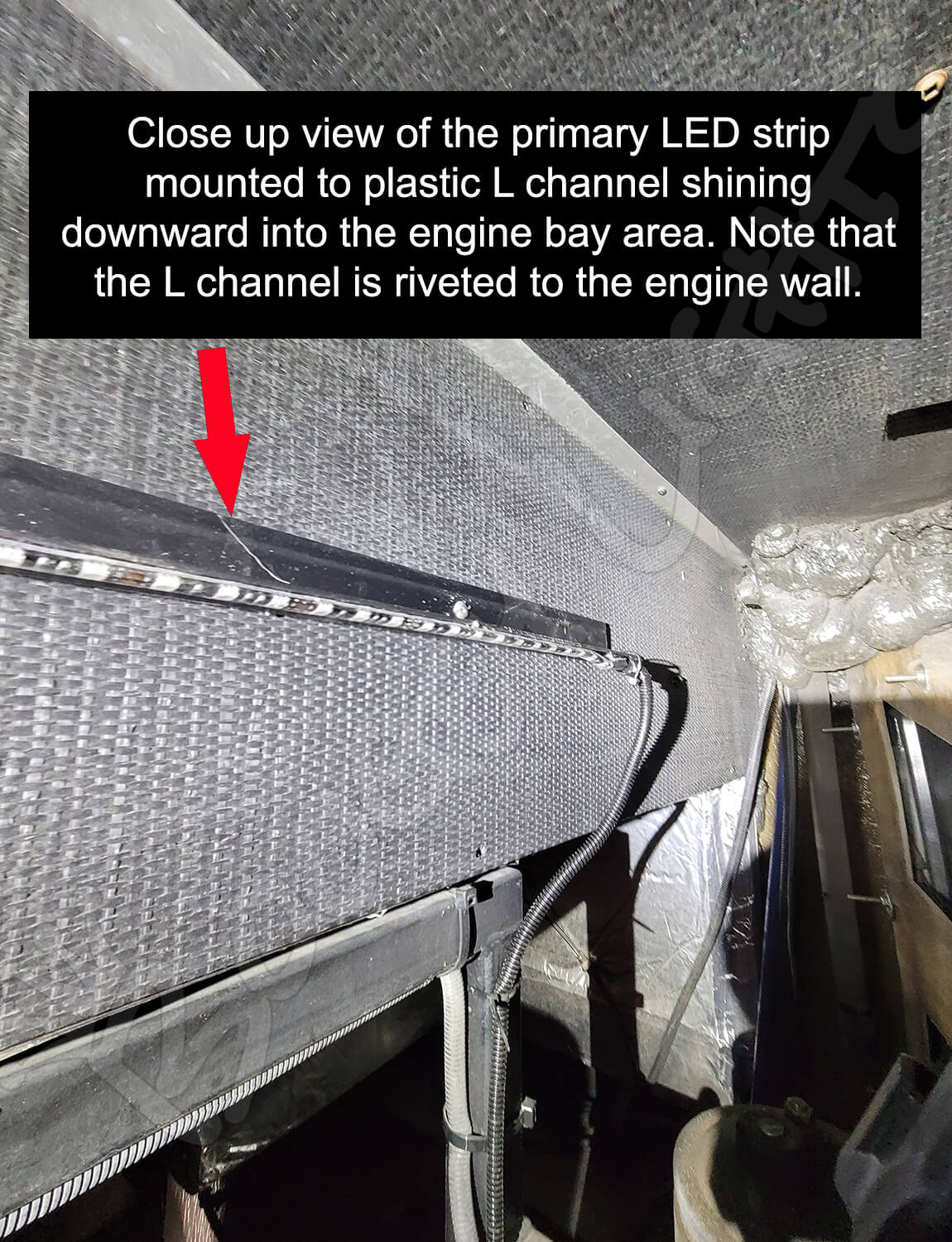
If you select YES, we will include black plastic L channel 2" longer than the length of your primary LED strip. This plastic L channel will be used to mount the primary LED strip above the engine bay area as shown in the photos in the previous section. The default is set to YES because the vast majority of installations will require this L channel to mount that primary LED strip. If however you don't need the plastic L channel, you can select NO and save a little money. We typically rivet this L channel to the back wall of the engine bay and the mount the primary LED strip to the bottom of it shining downward into the bay. We've included a couple of photos below so you can see what we are referring to.
Installation Tips
Installing the Boogey Lights® Engine Bay LED Light kit is one of the easier light kits to install primarily because the mounting surfaces are easily accissible from the engine bay. Typical installation time is about 60 minutes. Scroll down to view an installation video. You'll get a better idea of how we did it. You can also download the ENGINE BAY LED LIGHT KIT INSTALL GUIDE .
BEFORE YOU START
- WE STRONGLY SUGGEST BENCH TESTING YOUR LIGHTS AND CONTROLLER BEFORE MOUNTING! We cannot emphasize this enough. Probably 95% of all calls we receive from customers are about problems or issues that could have easily been avoided had the customer taken the extra 15 minutes to bench test their lighting setup before installation. Not only does bench testing give you an opportunity to understand the configuration, it also will flush out any problems or misunderstanding about the product and use before mounting.
- Make sure you know where your electrical connection will be. Most RVs (motorhome, travel trailer or fifth wheel) have an electrical access panel somewhere on the side of the RV where 12vdc power is available.
- Decide how you are going to connect the power lead coming from your LED light strip to the controller or power source.
- The only way to ensure the LED light strip stays stuck to the RV is to make sure you prepare the surface in accordance with the directions. Every LED light kit we sell includes 3M promoter (aka "primer"). It's absolutely critical the surface be prepared using this special 3M promoter and that you follow the directions provided with every light kit.
- If you need to cut the LED strip, make sure you do it before affixing to your RV. Our LED strips can be cut every 3 LEDs and are clearly marked.
- 3M Adhesion Primer. We provide small bottles of 3M Adhesion Promoter for our products. All you need is a shop rag, sponge or towel of some kind to apply the promoter to the surface. Once you paint on the promoter you have at least an hour to mount the light strip although we recommend proceeding immediately after painting the surface with the 3M Promoter.
- When in doubt, call our technical support team! We've done this thousands of times. We know what works.
CHOOSING THE MOUNTING SURFACE
When it comes to diesel pusher engine bay lighting, there is no one size fits all solution. Too many variables. The goal of engine bay lighting is to mount the LED strip(s) in a place where the glow from those light strips shine through the bay door structure without being able to see the actual LED light strips from outside the engine bay. This means the structure of the engine bay door largely determines where the LED strip(s) will need to be mounted and how many LED strips are needed to provide the glow you want. Some engine bay doors have large slots making it easier. Others have smaller slots and/or screens which require more carefully placed LED strips. For example, we've had to install the LED strip directly to the bay door in some cases in order to get the best glow effect. The LED strip needs a smooth flat mounting surface of about 1/2" wide so as long as you have a smooth flat surface that's at least ½" wide, you should be able to mount an LED strip to that surface.
Most engine bay lighting systems will have the primary (and longest) LED strip mounted at the top of the engine bay with the LED strip shining downward illuminating the engine bay. We do this using the supplied plastic L channel included with this kit and riveting that plastic channel to the back wall of the engine bay a few inches above the hinge point of the engine bay door. See photos below. On some engine bays it's possible to mount two vertical LED strips on each side of the bay both of them shining inward toward the center. An example of that type of installation is shown in the photo below. In other installations you may have to mount at least one led strip on the bay door itself to achieve the lighting glow you're looking for. Each bay is a little different. This light kit can be configured with up to four LED strips (only one is required -- the other three are optional). We've never seen an engine bay that required more than four LEDs strips.
MOUNTING THE L CHANNEL
We typically rivet this L channel to the back wall of the engine bay and the mount the primary LED strip to the bottom of it shining downward into the bay. We've included a couple of photos below so you can see what we are referring to. If you can't rivet the L channel, you may be able to use screws or even heavy duty 3M reclosable fastener. The challenge is that this part of the engine bay tends to get hot so anything that uses adhesive will eventually work loose over time – at least that's been our experience. Whatever you use to hold that L channel in place, make sure it's firmly attached.
CONNECTING TO THE CONTROLLER
The vast majority of Engine Bay LED light kits are used with existing RV under-glow light kits. We typically will connect all LED strips mounted in the engine bay area to one feeder cable which then connects to the existing under-glow light kit. In this way the engine bay lights will work whenever the under-glow lights are on. The one exception is if we're adding a separate cut off switch which will allow the user to turn off the Engine Bay light kit when the under-glow lights are on (not everyone wants the engine bay lights to always be on when the under-glow lights are on). In this scenario we'll install a simple on/off toggle switch in the engine bay area that breaks the ground wire running to the engine bay LED strips.
If you're installing this kit stand alone, the only difference is that you'll need to wire in the LED controller or on/off switch to power the LED strip(s) mounted in the engine bay area. We'll typically connect power to the engine starting batteries which are usually in or very close to the engine bay itself. While we generally discourage connecting any of our lighting systems to the starter batteries, most engine bay light kits contain relatively few LEDs so the voltage draw isn't all that significant. If however you're worried about reserving your starter battery power just for starting the motorhome, you'll need to find 12vdc power elsewhere. In these situations we recommend connecting to the house batteries but realize for a lot of motorhome configurations the house batteries are often 30+ feet away. We include a wiring diagram for the LED controller (if purchased). Be sure to refer to that wiring diagram.
Regardless of how you're wiring the lights, make sure all power leads are wrapping in split loom and zip tied firmly to an appropriate surface. We include split loom with every kit. You don't want any of the wires hanging loose inside that engine bay area. You also want to make sure that none of the power leads are near moving engine parts or too close to hot surfaces.
OPTIONAL TOGGLE SWITCH
In situations where the Engine Bay Light Kit is being connected to an exsiting Boogey Lights® lighting system (e.g. under-glow) there may be times when you don't want the engine bay lights to be on when the under-glow ligths are on. In this scenario we'll install a simple on/off toggle switch in the engine bay area that breaks the ground wire running to the engine bay LED strips. That toggle switch is usually mounted inside the engine bay area OR, installed in the bay door itself so the switch can be accessed without having to open the engine bay door.
VIDEO: Installing Engine Bay Lights
This is a short video showing an engine bay light kit installation.