


— Build Your Own Kit —
Build Your Own HORSE TRAILER Under-Glow LED Light Kit
We receive a lot of requests for full perimeter under-glow light systems on all kinds of vehicles. With so many vehicle and trailer types/styles on the market there are lots of variables; lots of options. Simply not possible to create a kit for all these various makes/models/layouts. To solve this problem we created this BUILD YOUR OWN KIT (BYOK) to assist customers with ordering the LED Under-Glow lighting and related materials they need for their specific vehicle chassis format. This product is specific to fifth wheel horse trailers (we offer them for RVs, motor-homes, food trucks and travel trailers too). This product is offered in two different chassis configurations for horse trailers: 2 axle fifth wheel and 3 axle fifth wheel. We suggest downloading the PDF diagram listed in the 'HOW TO PLACE YOUR ORDER' section below that matches your chassis layout to get started.
READ THIS BEFORE ORDERING!
Successful installation requires reading the written installation directions. While our How-To Videos offer helpful overviews, they do not replace the detailed documentation. Reading the instructions carefully is essential for proper fit, function, and long-term performance. Most support calls and warranty claims we receive stem from customers who don't read this information. Please take our advice and read the directions. We promise, you'll be happy with the results if you do.
FAQS | Frequently Asked Questions
While we encourage you to read all of the information presented on this product page (including the information on the navigation tabs), below are some of the most frequently asked questions we get about this product. In many cases, the answers to these FAQs will refer you to other sections of this product page for more details on the topic.
Do I really need to read the installation instructions?
I have a 36' triple axle horse trailer. Can you tell me what LED strip lengths I need to add under-glow to my trailer?
What are the power requirements?
How easy is this light kit to install?
I want the BLOOMER TRAILER configuration as shown in the product photo. What do I need?
What is Priority Processing?
PRODUCT CONFIGURATION
This product is offered in the following four configurations.
- Under-Glow: LED light attached to the bottom of the trailer providing an 'under-glow' lighting effect. This is the default option.
- Under-Glow + Wheel Wells: This adds Wheel Well lighting to the Under-Glow system.
- Under-Glow + Tail-Turn-Brake: This adds our Tail-Turn-Brake lights to the Under-Glow system.
- Under-Glow + Wheel Wells + Tail-Turn-Brake: This adds both Wheel Well lighting and Tail-Turn-Brake lights to the Under-Glow system.
The default configuration is just Under-Glow. If you add wheel wells and/or tail-turn-brake lights, additional drop down boxes will appear allowing you to select the length of LED strips you want for each. Scroll down to the HOW TO PLACE YOUR ORDER section to download a pdf diagram showing the layout of each of these configuration options.
HOW TO PLACE YOUR ORDER
The process to place your order is pretty straight forward. Follow these steps:
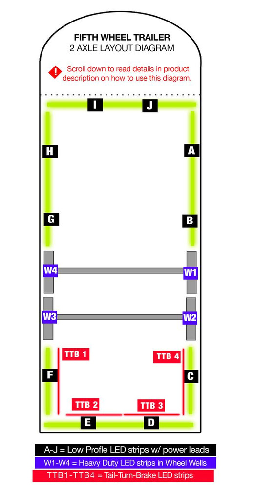
1. DOWNLOAD the PDF diagram that matches your trailer's chassis from this list:
2. Print out the PDF diagram you downloaded and then write down the measurements for each of the LED segments you want to light on your trailer where indicated by A through J AND W1 - W4 (or W6) if you want wheel well lights. See note below on what you need to know about taking those measurement. You do not have to use all segments.
3. Using the drop down boxes on this product page, select the LED segment lengths that match those on your diagram. Each LED strip has a 15' power lead hard wired to it. If your trailer layout doesn't use all of the segments listed on the diagram (many won't), simply leave those segments marked as 'none'.
4. Make your LED controller selection as well as your LED color selection.
5. Add to cart and check out.
If you want to light up the Goose Neck area too, we offer a separate GOOSE NECK UNDER-GLOW LED light kit which can be paired with this kit.
TAKING MEASUREMENTS | WHAT YOU NEED TO KNOW
It's super important when measuring your trailer that you look at the bottom of your trailer to examine the mounting area you have available. Yes, we know it's a pain to get on your back with a tape measure to do this but it really is the only way to get a good look and to get it right. We say this because you'll need to make sure you have a sufficient and appropriate surface area to attach the LED strips to your trailer. When doing so, make sure the area where you will be attaching the LED strip is clean and smooth (and free from sharp edges). The LED strip MUST be mounted flat against a single continuous mounting surface, in a straight line; it cannot bend around a radius or corners. Plus, the entire strip needs to be stuck to the mounting surface and not span across mounting surfaces. If you do, the strip will almost certainly fail in the spot that isn't affixed firmly to the mounting surface or, the point at which is spans across the two mounting surfaces. If you don't have a smooth, flat, contiguous mounting surface we recommend riveting or screwing 1.5" wide aluminum flat stock (or plastic flat stock) to the surface and then mount the LED strip to that flat stock. In some cases you may need to use aluminum L channel. More details about this can be found on the INSTALLATION TAB of the product page. The point is to carefully examine the bottom of your trailer when you're taking these measurements before placing your order.
The good news is that most horse trailers have a consistent, smooth mounting surface around the perimeter of the trailer you can use. There are usually cross-braces too you can use if you want to fill out even more lighting in the center of the trailer. That said, one challenge with some horse trailer construction is that if you mount the LED strip directly to that outer frame (shining downward), there's a good chance you'll be able to see the LED strip itself from the side view. This is because the frame chassis is either flush with or a little lower than the sides of the trailer. Our goal is never to see the LED strips themselves; only the glow from the LEDs should be seen. To avoid from being able to see the side of the LED strip, on some horse trailers we have to mount some L Channel first. The L channel rivets or screws into the frame of the trailer and then the LED strip mounts to that L channel. We have a video talking about this very issue. Click on the link below to see it (installation component starts at 2:20 into the video). We mention this issue now because you'll need to determine early on in the planning process if you can use the frame itself for mounting or if you need to install L channel first.
Once you have your measurements and have them written down on the diagram, you're ready to place your order using this product page. You'll notice each LED segment has a drop down box listing the available LED lengths from 1' to 16'. Yes, the maximum length of a single continuous LED strip with 300 LEDs is 16'. The laws of 12vdc electricity (voltage + amperage) as we know it today won't allow for longer lengths of 5050 LEDs using 12vdc power on modern day vehicles. This is why you'll notice our layout diagram has two LED segments in front of the first axle. Many trailers have longer distances than 16' in front of that first axle. If your trailer has more than 16' in front of the first axle, assuming you want full coverage, you'll need to use two LED segments in that space. For example, assume the distance in front of the first axle is 18'. If you want full coverage in that area, you'll need two LED segments to fill that entire space. How you configure those two LED segments in terms of the lengths is up to you. You can for example use two 9' LED segments - or - one 10' + one 8' - or - one 16' + one 2', etc. We suggest using a full 16' and a smaller LED length to fill out the entire area but it's not essential. For those LED segments that don't apply to your trailer, simply leave them set to 'none'.
For each LED segment, select the corresponding LED length from the drop down to what you wrote down on the diagram. For example, if LED SEGMENT A on your trailer is 14.5', you would select 14 from the drop down. Note that these LED segments are not precise in terms of the length. They will generally be a little less due to the power lead connection to the LED strip. It's not critical to have the exact length because the lights are so bright. If there's 5 - 10 inches of space that isn't covered, no one will know by looking at it. If however you're really concerned about this, order the longer length (e.g. 15' in our example here) and cut (and seal) the LED strip at the end where you cut. These LED strips can be cut in groups of 3 LEDs. That said, in the vast majority of cases, rounding down will rarely be noticeable and thus you won't have to cut the LED strips.
The kit includes additional 18 awg feeder cable to be used to connect the LED strips to the LED controller.
WHAT IS AN UNDER-GLOW LIGHT KIT?
What is an Under-Glow Light Kit?
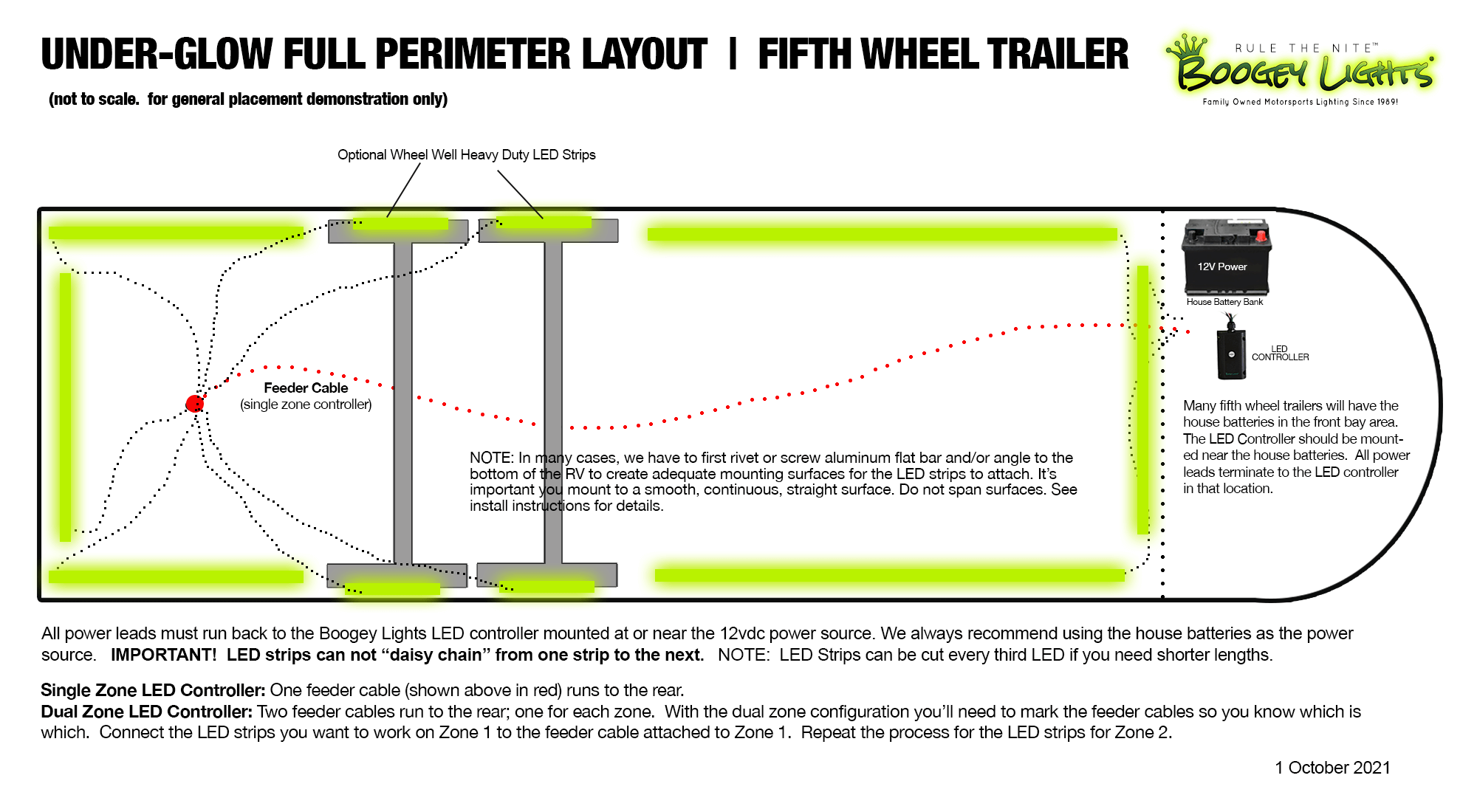
The Boogey Lights® LED UNDER-GLOW light kit is designed to attach to the bottom of a trailer and provide FULL-PERIMETER lighting around all four sides of the trailer. The Full-Perimeter LED Under-Glow kit is currently offered in RGB (multi-color, the default), RGBA (multi-color + amber), RGBW (multi-color + warm white) as well as single color versions. The kit includes your choice of two different LED CONTROLLERs: single zone or dual zone.
On full power these surface mounted hi-intensity super-bright RGB LED light strips provide an incredible amount of light in a wide variety of colors you control with the included RF wireless remote control and smart-phone Bluetooth controller. In addition to the wireless RF remote control that's included, the LED controller is also bluetooth capable. This allows you to control your under-glow lights with your bluetooth capable smart-phone and our free APP (IOS or Android). All Under-Glow LED controllers offered include Bluetooth. The Single Zone Heavy Duty LED Controller is the default LED controller included with the kit. This Single Zone Heavy Duty LED Controller will power up to 1800 LEDs and comes with your choice of our standard 3vdc M7 hand held RF remote OR two, 12vdc KEYFOB wireless RF remotes (see details below on the differences). There is an optional Long Range M7 RF remote available. The Long Range M7 RF remote will at least double the effective range of the wireless remote. Boogey Lights® RF Controllers will display seven colors (steady on + four lighting effects): RED, GREEN, BLUE, WHITE, LIGHT BLUE, BOOGEY LIGHTS GREEN (LIME GREEN/YELLOW), HOT PINK/PURPLE. The lighting effects options for our RF Controller include: DIMMING, BLENDING, BREATHING, STROBING. In the Blending, Breathing and Strobing modes these features can be set to remain on a single color or to cycle through each of the 7 colors. You can also adjust the speed at which this happens. The RF remote control offers SEVEN levels lighting effects (e.g. 7 levels of dimming). For the DUAL ZONE Heavy Duty LED controller, these functions work independently per zone OR both zones together.
TAIL-TURN-BRAKE OPTION
You'll notice we offer the option of adding up to four RED led strips to the bottom rear of the trailer (see layout diagram). This is for tail-turn-brake integration. These RED led strips can be wired to the trailer's tail, turn and brake light and operate independent from the under-glow light system. Each RED LED strip has three diodes such that each diode can be connected to the trailer's tail, turn and brake lights. Wiring details can be found on our website here. We offer instructions for both 3 and 4 conductor circuits. Additional details can be found on the INSTALL tab of this product page.
Keep in mind that adding additional LEDs to your trailer's tail-turn-brake wiring may exceed your tow vehicle's rated amperage for that lighting circuit and throw an error because the lighting control module (LCM) 'thinks' there is a problem with your electrical system due to the increase in amperage draw. In these cases the easiest work around is to add an independent relay (3 or 4 relays depending on how your tow vehicle is setup) to the circuit to make them work. The relays draw milliamps and won't cause the LCM to error out. This problem is most likely to occur with newer tow vehicles. If your tow vehicle is 2015 or newer, we strongly suggest adding relays to your installation initially. We offer heavy duty relays for sale on our website here but they can also be purchased at any auto parts store. They're very common. Don't wait until after you do the install to find out your truck's LCM doesn't like the additional amperage draw you've just added.
SINGLE ZONE OR DUAL ZONE?
This kit offers both SINGLE ZONE and DUAL ZONE controller options. As the names suggest, a Single Zone controller has just one single lighting zone. All LEDs wired to the controller are on one zone. Whatever color or feature set you apply will be what you get on all leds. Pretty simple. With our Dual Zone controller, you can set up and operate two distinct lighting zones which can be operated and controlled individually or together. With the Duty Dual Zone LED Controller you have more flexibility as to how you want to control your Boogey Lights. On a Dual Zone controller each lighting zone is capable of supporting up to 1500 LEDs for a total of 3000 LEDs. It will work with your Android® or iOS® Smart-phone. It will also work with the included M7 Style RF wireless remote. Details on features are below.
LED CONTROLLER FEATURES
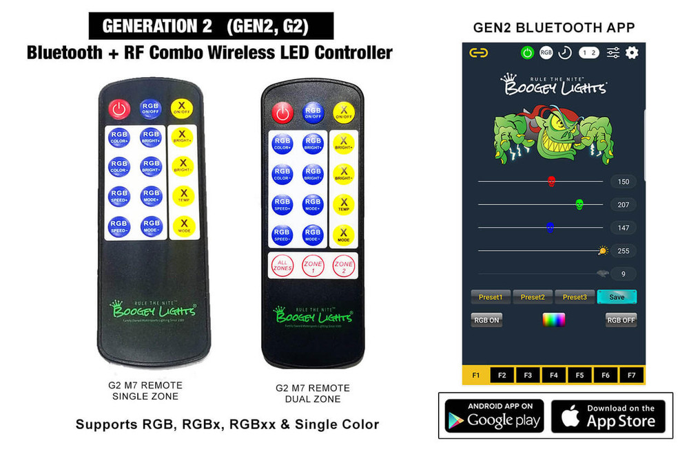
Bluetooth + RF Combo Wireless Control
The LED Controllers offered in this kit are our GEN2 Single Zone and Dual Zone Heavy Duty Bluetooth COMBO LED Controllers. COMBO means they can be operated using either the included M7 RF wireless hand held remote OR your Bluetooth enable smart-phone (and our free APP). Both will work. The RGB version is capable of displaying 16 million different color combinations. The GEN2 RGBx version can display even more color combinations depending on the type of LED strips connected to them. In addition, lighting effects on the Bluetooth controller are significantly more controllable in terms of speed and intensity. Each color and lighting effect is controlled by "sliders" or a color square on your smart-phone screen so you can adjust the speed and intensity to get the lighting the way you want it.
Key Features & Capabilities
- Our GEN2 LED Controllers are based on the Bluetooth 5 chip set family which provide fast response times and the best possible RF/Bluetooth transmission distance.
- The SUPER and HEAVY DUTY GEN2 Controller can support Single Color, RGB, RGBx and RGBxx LED strips with both RF and Bluetooth control.
- The HEAVY DUTY controller versions include two antennas: a screw-on 2" stubby antenna and an extended magnetic mount antenna with 15' of wire for optimal reception on any vehicle.
- Use the included RF wireless remote to quickly turn on/off/dim your Boogey Lights. You can also select up to 7 different preset colors using the RF remote as well as access 7 different lighting features.
- Use your smart-phone to operate your Boogey Lights®: On, Off, Dimming, Color Selection, Brightness, Speed, Color Programming, Timers
- Adjust the color sliders or color square to select the color you want.
- Access additional lighting features (e.g. strobing, flashing, breathing, morphing) modes using the 7 Function Keys.
- Save your favorite lighting configuration using Pre-Sets
- Countdown Timer and a 24 hour On/Off Timer function
- Quick-Switch feature for use with RGBx LED strips.
- Password protection to stop others from connecting to your LED controller.
- Programmable Color Rotation mode offers the ability to program the controller to display two or three colors of your choice and then rotate those colors in sequence.
- Assign a 'nick name' to your controller so you can easily find it when scanning.
- Set the APP to auto-connect to your LED controller every time you launch the APP on your phone
- DOWNLOAD the GEN2 LED Controller Operating Manual & Wiring Diagrams
- DOWNLOAD the GEN2 Bluetooth Operating Manual
- DOWNLOAD the GEN2 M7 RF Wireless Remote Operating Information
- VIEW the GEN2 LED Controller Series Product Page
- VIEW the GEN2 BLUETOOTH APP Information Page
COLOR OPTIONS & CONSIDERATIONS
This light kit is offered in eight single color options and in three multi-color configurations: RGB, RGBW (RGB + warm white) and RGBA (RGB + amber). For the single color options the LED controller wireless RF remote will give you the ability to turn the LEDs on/off as well as dim, flash, strobe and breath (and change the speed at which those features work). With the bluetooth APP, you can perform these same functions as well as save presets. For the multi-color options, you have the same capabilities however the feature set is significantly expanded since you also have the ability to change/adjust/tweak the colors you want to display. With the included RF wireless remote you can change between 7 pre-set colors (Red, Green, Blue, White, Light Blue, Lime Green/Yellow, Hot Pink/Purple) and functions of on/off, blending, strobing, breathing, flashing, fading and dimming. You can also use your Bluetooth enabled smart phone to create a custom look. The Bluetooth APP allows you to program the RGB diodes of any of our RGB, RGBW and RGBA strips with over 16 million different color combinations plus three pre-sets. Also, the Bluetooth APP offers 2 and 3 color rotation programming along with two timer features. Click the BLUETOOTH APP navigation tab on this product page for significantly more information on both the Bluetooth capabilities and APP functionality (including a video showing how the Bluetooth APP works)
RGBW: On the RGBW led strip, in addition to RGB, you get one extra diode which is Warm White. That warm white diode has a Kelvin temperature of 2400 which means it has a yellowish look giving it a warmer, softer, candle like look (see photo below). That fourth diode on the RGBW led strip can be wired directly to our GEN2 LED Controller which supports RGBx LEDs. As an option, you could also wire that fourth diode to a completely separate on/off switch. Your choice. You could also use the Quick-Switch feature with this fourth diode too. If you select this LED color option, you'll be prompted to make a RGBx Switch selection too. The next text block explains these options.
RGBA: On the RGBA led strip, in addition to RGB, you get one extra diode which is AMBER. That fourth diode on the RGBA led strip can be wired directly to our GEN2 LED Controller which supports RGBx LEDs. As an option, you could also wire that fourth diode to a completely separate on/off switch. Your choice. You could also use the Quick-Switch feature with this fourth diode too. If you select this LED color option, you'll be prompted to make a RGBx Switch selection too. The next text block explains these options.
RGBx SWITCHES
If you select the RGBx (RGBA or RGBW) LED color option you'll see a PRODUCT OPTION box appear asking you to make a RGBx Switch selection. You have three options as follows:
- Use the GEN2 controller to operate the X diodes.
- Add a ON/OFF TOGGLE Switch to use with the Quick Switch feature built into the GEN2 controller.
- Add a ON/OFF WIRELESS Switch to use with the Quick Switch feature built into the GEN2 controller.
One of these three options must be selected. The 'Pick One' or 'Not Applicable' options cannot be purchased with the RGBx LED Option.
At the very minimum, select OPTION 1 (using the GEN2 controller to operate the X diodes). The GEN2 LED Controller will allow you to operate the X diodes (Amber or Warm White) using the RF Remote or our Bluetooth APP. You can however add another switch to the kit which can be used with the Quick Switch feature built into the GEN2 controller. The Quick Switch feature requires a separate on/off switch to activate the feature. Details about this QUICK SWITCH feature and how to use it along with a wiring diagram are in the next text block on this product page. If you are purchasing RGBA or RGBW LEDs, we strongly suggest taking the time to at least read about it. It's a popular feature that is unique to Boogey Lights® LED lighting products.

USING THE QUICK-SWITCH FEATURE
The Quick Switch feature is available on our GEN2 SUPER, HD SINGLE ZONE and HD DUAL ZONE LED Controllers. Whatever color LED you have connected to the GREY output wire of the GEN2 Controller is the color that will display when the Quick Switch is triggered with 12vdc +. The most common use for this configuration is with commercial vehicles who want to be able to instantly turn off whatever color they're running and turn on a DOT compliant AMBER which is on our RGBA LED strips. For these installations, the yellow trigger wire is connected to a toggle switch or other wireless switch that activates the AMBER leds. You can also do the same thing with the RGBW product. When the Quick Switch trigger wire is not energized, the LED controller operates the RGBxx diodes normally.
PRE-BUILT LED CONTROL CENTER
We offer the option of pre-building the LED Control Center with your order. These LED Control Centers make for a professional looking installation. Also makes the installation a little easier for DIYers since the controller wiring is neatly organized and easily identifiable. It's also a huge time saver. Can easily save two hours (or more) when doing a typical installation.
The pre-built Control Center has the LED Controller and power connections mounted to a PVC board. The power connections make it simple to connect your battery power as well as the LED strip power leads via a terminal blocks mounted to the board. Simply strip the end of the battery lead cable and LED strip power leads, push them into the terminal block and tighten the screw. This design also makes trouble shooting easier. The board has four 2" stand offs with plexi-glass mounted on top which keeps the components protected. You can read more about this option on the LED CONTROL CENTER product page. We include some photos below. The LED Control Center option is only available when an LED Controller and/or relays are ordered.
ADD SWITCH TO CONTROL CENTER?
This option applies to your order ONLY IF the following conditions are met:
1. You are ordering RGBA or RGBW LEDs.
2. You are ordering the ON/OFF TOGGLE switch or the RF WIRELESS ON/OFF switch for integration with the Quick-Switch feature.
3. You are ordering the Pre-Built LED Control Center.
If all of these conditions are met, we need to know if you want the ON/OFF Toggle switch (or ON/OFF Wireless switch) mounted physically to the LED Control Center.
If you select YES for either:
- TOGGLE SWITCH: It will be mounted to the clear plexi-glass cover and wired to the Quick-Switch trigger of the LED controller.
- WIRELESS ON/OF: The module for this switch will be mounted to the LED Control center board and wired to the Quick-Switch trigger of the LED controller on the board. The wireless RF key fobs will be used to operate the Quick-Switch.
If you select No, we will include the switch you ordered with the kit and you'll be able to mount them wherever you want.
NOTE: If you order the Wireless On/Off switch, we suggest having us mount the module to the LED Control Center Board.
WHEEL WELL LIGHTING

We offer the option of adding wheel well lighting to your full perimeter light kit. It can be done for one, two or three axles; motor homes and fifth wheel trailers. Sold per pair. With the exception of RGBW, we use our HEAVY DUTY LED Strips for this purpose (RGBW uses low profile). Be aware however that not all trailers will be able to accommodate lights mounted in the wheel wells. You'll need to measure the amount of clearance you have between the tire/wheel and the trailer to see if there is enough room to get into the wheel well to do the installation (without removing the tire/wheel). Assuming your trailer has enough clearance to work, the next thing you need to consider is the mounting location. For maximum lighting effect we prefer to mount the Heavy Duty LED strip straight up from the tire and off set a little toward the outside wall of the trailer. This minimizes the possibility you'll be able to see the LED strip directly and instead, only see the glow from the LEDs flooding the tire/wheel well area. Next you'll need to consider the mounting surface. Is it clean? Smooth? Will 3M tape (promoted with 3M adhesion primer first of course) adhere to that surface? Some trailers are under-coated which can make it difficult to get the LED strips to adhere to the surface without first having to scrape the under-coating away and/or screwing the LED strip to the wheel well at each end. Others have a type of material covering the wheel well surface itself. In this case you may need to cut that material away first to get to the smooth surface beneath it. You'll need to look closely at your trailer to make this determination. It is not something we can assist you with based on the model. The last thing you want is for that LED strip to come loose from it's mounting location just above the tire/wheel as you drive down the road. The final consideration is length. How much room do you have to mount the LED strip? You need at least 12" (15 LEDs) for the smallest strip and 53" (75 LEDs) for the maximum length. We typically use 12" or 22" for wheel wells.
Once you've confirmed the above, make your selection from the drop down options for this product. You'll notice we offer five LED strip length options PER AXLE wheel well. They're ordered per wheel well. Do not assume that just because a 32" led strip will fit in the wheel well for one of the axles, the same will fit in another.
What is Priority Processing?
If the product configuration of the light kit you're purchasing is eligible for PRIORITY PROCESSING, you can select 'YES' (default is 'NO') and that light kit will be given priority in our build queue such that we'll build and ship the light kit using the shipping method you select at checkout within TWO business days (or less) regardless of what the current build time estimate states. You can read more about our BUILD TIME ESTIMATE here.
Business Day Note: The 'Business Day' cut off time is NOON Eastern. If for example you place your order before noon on Monday, we'll build and ship your order no later than Wednesday. If you place that same order after 12 noon eastern on Monday, we'll build and ship your order no later than Thursday. If for some reason we're unable to do this (e.g. out of stock item or some other limitation), we'll reach out to you via email to ask how you want to proceed: Either cancel the order or ship the order normally and refund the Priority Processing fee paid.
Be aware that not all product configurations are eligible for Priority Processing. For example, if your light kit has an LED CONTROL CENTER in it, we do not offer Priority Processing on that order. Also, we exclude high demand lighting components that are often purchased in bulk by commercial accounts (eg. RED 75 Heavy Duty LED strips).
Priority Processing is offered per line item, not per order. If your order has multiple LED light kits or LED strip components on it, only those products that are eligible for Priority Processing (and selected as YES) will be shipped within the two business day time frame. Any remaining light kit products will be shipped via ground per our normal build time estimate. If your order has other non-LED components on it (e.g. controllers, switches, replacement parts, wire, 3M primer, etc), we will ship them with the priority processing item.
Does this mean that orders placed ahead of mine are being pushed back?
If I upgrade my shipping to 2 day or overnight, does this speed up the build time?
THE KELVIN SCALE
Color temperature is a method of describing the color characteristics - warmth or coolness - of a white light source. Commonly referred to as the Correlated Color Temperature (CCT), it's a gauge of how yellow or blue a white light source appears to the human eye. The spectrum of color temperature is assigned numerical values, measured in degrees of Kelvin (K), on a scale of 1,000 to 10,000. Most Kelvin temperatures for modern lighting applications however fall somewhere on a scale of 2000K to 6500k. The color temperature of a light source lets us know what the look and feel of the light produced will be.
On the low end of the scale, from 2000K to 3000K, the light produced is often referred to as a "warm white", "soft white" or sometimes called a "candle white". It ranges from orange-ish to yellow-ish white in appearance. This kind of light is inviting, comfortable and relaxing.
In the middle of the scale, from 3100K to 4500K, the light produced is often referred to as a "neutral white" or "natural white". Light sources within this range will emit a more neutral white light and may even have a slightly blue tint. This kind of light is bright, vibrant and clean appearing.
At the top end of the scale, from 4600K and above, the light produced is referred to "cool white", "bright white", "pure white" or "day white". Light sources in this range will have a blue-ish white tint to them. The higher the number, the more blueish it will appear. This kind of light will appear crisp, invigorating and energetic. It's most commonly used for workspace lighting.
VIDEO
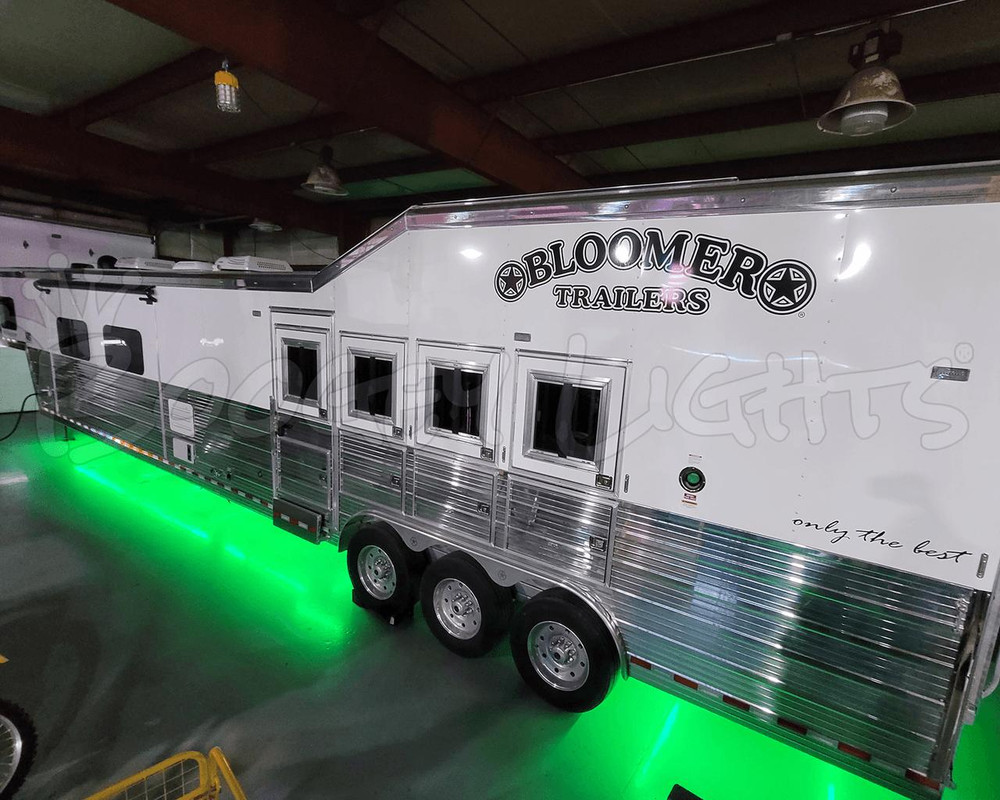
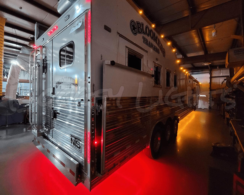
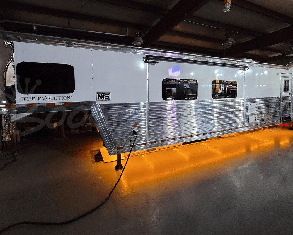
This is a 5 minute and 34 second tour of a recent Boogey Lights under-glow installation on a 2023 52' BLOOMER HORSE TRAILER. This video tour includes a review of the installation process including a view from underneath the trailer. We installed our RGBA product along with Tail-Turn-Brake integration. This unique RGBA LED product provides up to 16 million color combinations using the included RF + Bluetooth wireless controller. Best of all, with a flip of a switch, all of the lights will instantly change color to AMBER. Check out the video.
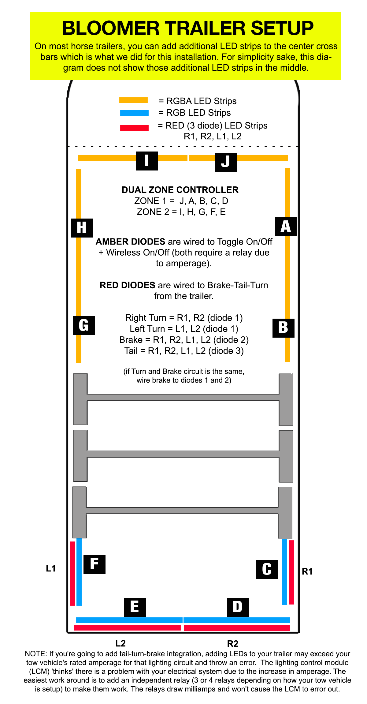
BLOOMER TRAILER CONFIGURATION
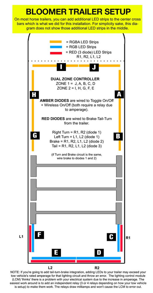
If you want the same look (RGB dual zone split front and rear, Amber only in front, Red only in rear with Tail-Turn-Brake functionality) as you see on the 52' BLOOMER TRAILERS horse trailer shown on this product page, the LED strips in front of the axles all need to be RGBA. The RGB diodes of these LED strips are split between ZONE 1 and ZONE 2 on our Dual Zone LED Controller (Zone 1 = drivers side. Zone 2 = passenger's side). The A diode is wired to an on/off switch of some type (we used a dual switch setup with both a toggle on/off and a wireless on/off). The LED strips in back of the axles need to be a combination of RGB and Single Color RED. The RGB LEDs are wired to Zone 1 and Zone 2 of the Dual Zone controller just like the front RGB strips are. The Single Color RED leds are what are wired the trailer's tail-turn-brake lights. These single color LED strips have three diodes in them. One diode is wired to the tail lights and the other two diodes are wired to the brake and turn lights. If you're going to add this tail-turn-brake integration, keep in mind that adding additional LEDs to your trailer may exceed your tow vehicle's rated amperage for that lighting circuit and throw an error because the lighting control module (LCM) 'thinks' there is a problem with your electrical system due to the increase in amperage draw the LEDs are pulling. In these cases the easiest work around is to add an independent relay (3 or 4 relays depending on how your tow vehicle is setup) to the circuit to make them work. The relays draw milliamps and won't cause the LCM to error out. This problem is most likely to occur with pickup truck tow vehicles. If your tow vehicle is a pickup truck - particularly one built in the last 10 years - we strongly suggest adding relays to your installation initially. Don't wait until after you do the install to find out your truck's LCM doesn't like the additional amperage draw you've just added.
Note: This product page won't allow the above exact configuration to be ordered; although you can come close by ordering RGBA all around (with Dual Zone LED controller) for under-glow and then include the four Tail-Turn-Brake LED strips in the rear. If however you want the exact same configuration as the 52' BLOOMER trailer the solution is to order the RGBA + Dual Zone LED controller using this product config by completing the lengths of LED SEGMENTS A, B, G, H, I, J (and wheel wells if you want those too) along with the four RED LED strips for tail turn brake (TTB1 - TTB4). Then, order the RGB strips individually using our LOW PROFILE LED STRIPS. It's not as complicated as it sounds but if you're totally confused and you want help, reach out to us. We can build the draft cart for you.
You can DOWNLOAD the layout and wiring diagram of the BLOOMER TRAILER we did on the trailer shown on this product page. You can also find this same diagram in the photo carousel of this product page.
DOT COMPLIANCE
The AMBER and RED single color LED strips are DOT COMPLIANT. They conform to applicable provisions of the Federal Motor Vehicle Safety Standard 108 requirements.
THE KELVIN SCALE

USING 3M ADHESION PRIMER
To achieve the full adhesive strength of the 3M® tape affixed to the back of each strip 3M® Adhesion Promoter (aka Primer) must be applied to the mounting surface first. This is an important step to ensure a secure bond. The 3M® Adhesion Promoter creates a chemical bond between the tape and the mounting surface such that the LED strip will stay stuck (at least until you decide you want to remove it). Using any other solvent such as rubbing alcohol or acetone is not the same thing as using 3M® Adhesion Promoter. While these solvents will help clean the surface, they do not prime the surface. There is a difference. 3M® Adhesion Promoter is included with this kit although you may elect to purchase more if you'd like.
OTHER ITEMS YOU MAY NEED
No two installation scenarios are the same. Not everyone shares the same installation quality goals. Some folks are OK with twisting wires together, others want to solder them. Some folks are OK with running wires where they may be seen or unprotected to save money/time, others want a tidy, clean install without any wires showing. Some folks are OK with mounting their LED strips to whatever surface they can find, others want to take the time necessary to build out appropriate mounting surfaces to provide the best lighting effect on their vehicle. The point is it's not possible to provide all the materials necessary for all installation scenarios and quality goals. Our light kits provide the essential components needed for a high-quality, functioning lighting system. Installation of our light kit to your specific vehicle may however require additional items to make it look and fit the way you want. This is particularly the case with electrical wiring and mounting of LED strips. Before proceeding with your installation we suggest you consider THESE OTHER ITEMS.
IMPORTANT WARRANTY NOTE FOR COMMERCIAL VEHICLES
These low-profile surface mounted LED strips are not built to withstand significant flexing or lateral movement of the surface the strip is mounted to. Some examples include on semi-truck trailers as well as tow trucks where there is significant movement, bending or flexing of the surface to which the strip is mounted. Also, the strip can not be mounted in such a way as they span multiple mounting surfaces. Mounting them this way will virtually guarantee the strip will fail sooner rather than later. These strips must be mounted to one single continuous smooth, clean, flat, straight surface and in an area that is protected from corrosive chemicals. Commercial vehicles that frequently travel roads treated with corrosive chemicals often used for melting snow and ice can impact the durability of these LED strips if the strips are mounted in an area that is exposed to these chemicals. Hi-Intensity Strips that fail in these operating environments ARE NOT COVERED UNDER WARRANTY. For these types of operating environments we recommend (and warranty) our HEAVY DUTY LED strips.
NOTE ON EXTENDED USE
The LEDs used in this product are very bright; the brightest 12vdc LED lights available. They're designed to be used for accent lighting applications where they are typically powered on for a few hours (usually on a dimmed setting) and then powered off. While they can be used in functional lighting applications (e.g. bright white to temporarily illuminate a work area), the lights should NOT be left powered on for extended periods of time (e.g. 6+ hours). If the LEDs are left powered on for long periods of time - particularly on their brightest setting - the LEDs closest to the power source will have a burned look to them over time. This is because the amount of voltage being pulled through the LEDs closest to the power source will be higher than the voltage going through the LEDs further down the strip. The end result is that those LEDs closest to the power source will be hotter thus creating the burned look. This will occur mostly when displaying the color white on a full brightness setting but can also occur with other colors. For this reason, we do NOT suggest leaving these LED lights powered up for extended periods of time particularly on their brightest setting. Burned looking LEDs is NOT covered under warranty.
Installation
YOU MUST HAVE AN UNDERSTANDING OF 12V POWER. An essential skill with installation of any Boogey Lights LED products is knowing how to correctly wire the product to a 12vdc circuit. This includes understanding the importance of having a properly sized fuse at the power source, polarity, how to properly seal an electrical connection, using properly sized wire gauge for the load, measuring voltage and measuring the additional amperage draw you're adding. If you are uncertain or unfamiliar with any of these concepts, we urge you to ask someone who has the knowledge to assist you onsite. We cannot advise you on these matters remotely.
There is no set installation configuration. Whether you have a motor home, bus, 5th wheel, tag-along travel trailer, utility trailer, food truck or semi-truck the configuration concepts are pretty much the same. Your rig and your imagination are the only limits. It is important however to identify where you're going to mount the LED strips as well as where the LED controller will be located. You may want to check out our section of HOW-TO VIDEOS which many customers find helpful with deciding how they want to install their Under-Glow lights.
⚠️ We strongly encourage you to read the Installation Instructions before proceeding. The vast majority of folks who have problems with this product are those who ignore our advice here.
Install Documentation
All of our installation documentation for this product (and all others) is available to download directly from our website. We encourage you to download this information and review before placing your order. That way you'll have a solid understanding of what is required (and no surprises). Here are some of the most important installation documents for this product. Note that while some of the documentation here references RVs, whether it's a fifth wheel RV or a horse trailer, the concepts are all the same. The lighting system is installed the same way regardless of whether the trailer is for horses, cargo or people. You will find ALL available documentation in our INSTALLATION RESOURCES SECTION.
- Under-Glow Kit Install Guide
- Full Perimeter Install Guide
- Know your power consumption
- How to Mount on Coroplast
- What you need to know before mounting your LED strips
- How to cut your Low Profile LED strips
- DOWNLOAD the GEN2 LED Controller Operating Manual & Wiring Diagrams
- DOWNLOAD the GEN2 Bluetooth Operating Manual
- DOWNLOAD the GEN2 M7 RF Wireless Remote Operating Information
You may also want to check out our section of HOW-TO VIDEOS which many customers find helpful with deciding how they want to install their Under-Glow lights.
Creating a Mounting Surface
About the LED Strips
Some things to keep in mind:
- Our Hi-Intensity LED strips can be cut every 3 LEDs to accommodate shorter runs. If you cut the strip, make sure you cut where indicated and seal the end with heat shrink or similar substance. Important moisture not get into the strip.
- Detailed specifications can be found on this PRODUCT SPECIFICATIONS page OR by clicking on the SPECS navigation tab appearing on this product page.
- The maximum length of one Hi-Intensity strip is 16'. Multiple 16' strips CAN NOT be daisy chained together. If you want to do a run longer than 16', you can butt two strips together to get the desired length. That said, we've rarely seen an installation that required doing this for a lack of light. Boogey Lights® LEDs are so bright that one 16' strip should provide more light than you'll need. Simply centering one 16' strip will in most cases be sufficient.
- The maximum number of 16' LED strips that can be powered at one time depends on which controller you're using. Our Single Zone Heavy Duty controller will power at least six 16' LED strips. You might be able to get 7 depending upon your wiring. That said, it's possible to add additional controllers and manage those controllers with one RF remote. Lots of possibilities. The limitation ultimately comes down to your power source.
- Be mindful of where your power source is located as well as where you will be mounting the controller. The power lead for each Hi-Intensity strip needs to connect directly to the controller at your power source. Knowing where your controller will be mounted in relation to where the LED strip will be placed will determine how much power lead cable is needed on each LED strip.
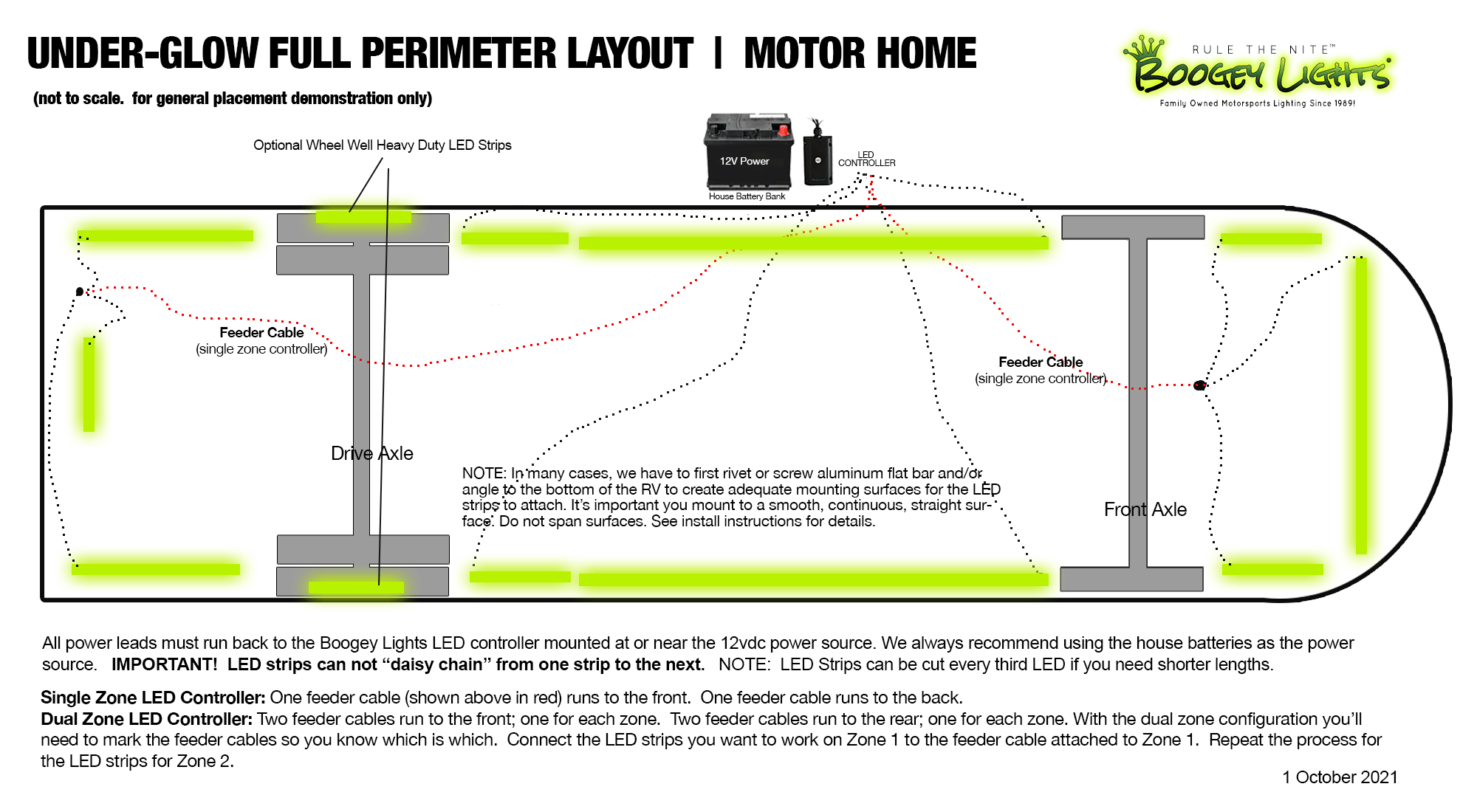
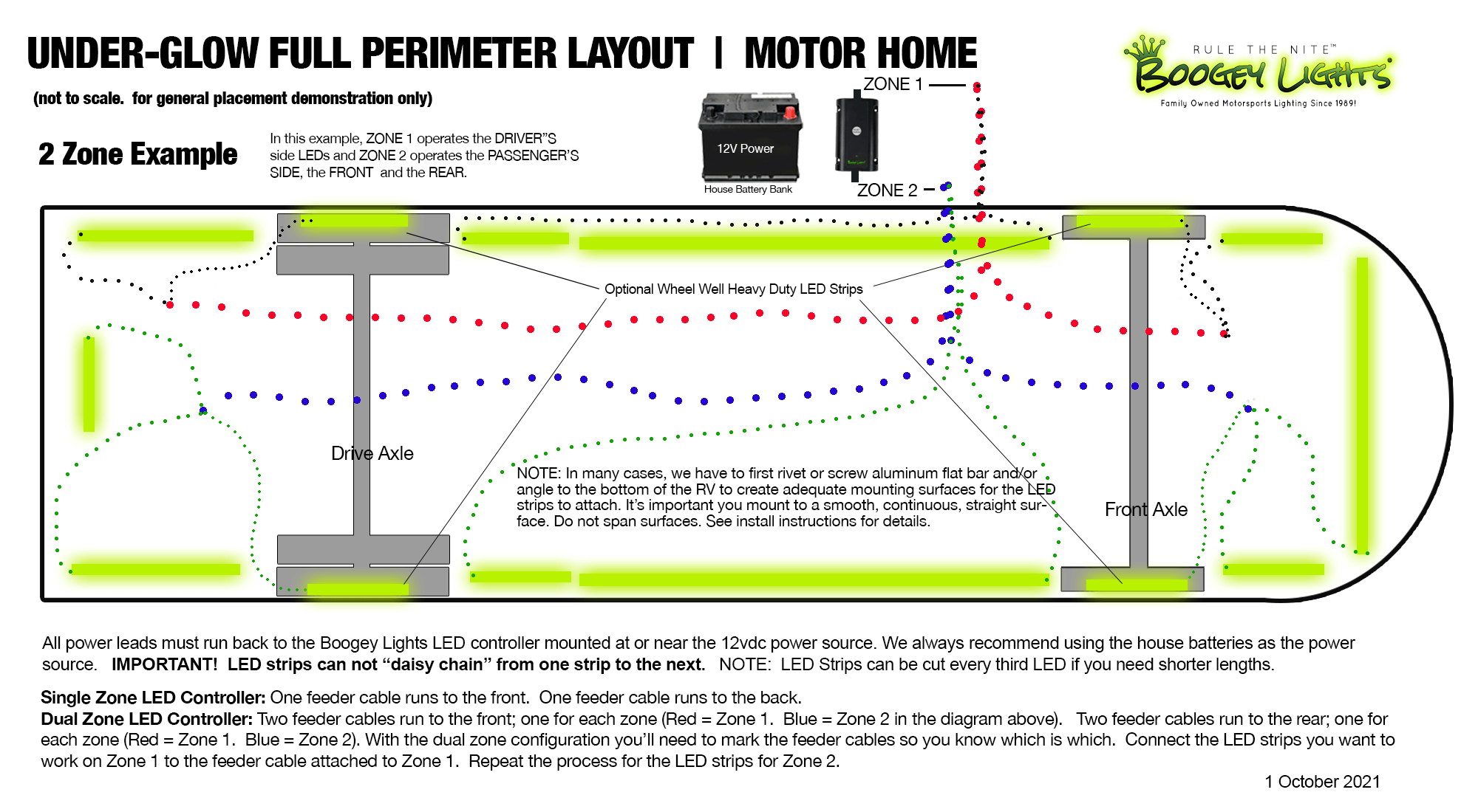
- We include a couple of images (see below and the carousel of images of the product itself) of examples of wiring diagrams for both a single zone and dual zone controller installation to give you an idea of how the LED strips, LED controller, Power leads and Feeder cable connect to each other.
Before You Start
Installing the Boogey Lights® LED UNDER-GLOW trailer kit is relatively straight forward. Installation time for a full perimeter under-glow system is typically 6 to 10 hours depending upon complexity of your configuration. Some things to keep in mind before you start.
- The Under-Glow trailer kit is intended to be installed on the bottom of an trailer, camper or trailer. Make sure you have adequate area where to affix the LED light strips. You'll need to make sure you have sufficient surface area to attach the LED strips. In addition, the area where you are attaching the LEDs needs to be reasonably clean and smooth (and free from sharp edges). If not, the LED strips won't stick. The LED strip MUST be mounted flat against a single contiguous mounting surface, in a straight line. Really important the entire strip be stuck to the mounting surface and that you NOT attempt to span across mounting surfaces. If you do, the strip will almost certainly fail in the spot that isn't affixed firmly to the mounting surface (or, the point at which is spans across the two mounting surfaces). If you don't have a smooth, flat, contiguous mounting surface we recommend screwing 1.5" wide aluminum flat stock to the surface and then mount the LED strip to that flat stock. This aluminum flat stock can be purchased at just about any home improvement store or, we offer it for sale online too. Also, do not attempt to mount the strip to follow a radius. The LED strip has to be mounted in a straight line and flat. Failing to follow these mounting instructions will almost certainly result in a damaged LED strip which is not covered under warranty.
- Think about where you're going to be mounting your LED CONTROLLER. If that location is in an enclosed metal storage box or is surrounded mostly by metal, you're likely going to want to purchase the LONG RANGE REMOTE and an LED CONTROLLER that has the Extended Antenna option. Our LED Controllers work on radio frequencies. Radio frequencies don't go very far when they are enclosed in metal. We strongly suggest testing the effective range of your RF remote/LED controller BEFORE permanently mounting it. If you're not getting the range you'd like, either relocate the LED Controller or purchase the Long Range Remotes and/or Extended Antenna.
- Make sure you know where your electrical connection will be. Most trailers (motor home, travel trailer or fifth wheel) have an electrical access panel somewhere on the trailer where 12vdc power is available. We prefer to make all of the electrical connections where the house batteries are located. This isn't a requirement but generally works best as you can tap directly into 12vdc power directly from the battery bank. If you are going to use 110vac, make sure you have ample room to mount/affix the power converter box. The 110vac to 12vdc power converters we sell for this kit are 10amps. If you are going to max out the heavy duty controller with LED light strips you'll need to run TWO power converters in parallel (for a total of 20amps). If you have questions on this, please call us. We'll be happy to assist you!
- Decide how you are going to connect the power lead coming from your LED light strips to the power source. Most trailers have access into the electrical closet from underneath the trailer itself. If so, this is the perfect place to run your power cables. Important to remember that the remote control units are not water proof so you want to mount the controller box in an area that will remain dry.
- The only way to ensure the LED light strip stays stuck to trailer, camper or trailer is to make sure you prepare the surface in accordance with the directions. Every LED light kit we sell includes 3M adhesion promoter (aka "primer"). It's absolutely critical the surface be prepared using this special 3M promoter and that you follow the directions provided with every light kit. For the power lead wires that feed the LED strip we include some extra 3M tape and zip tie mounts.
- If you need to cut the LED strip, make sure you do it before affixing to your trailer. Our LED strips can be cut every 3 LEDs and are clearly marked.
- AMPERAGE Data for all Boogey Lights products can be found on our website.
- 3M Adhesion Primer. If you're using the 3M promoter tubes (vs bottles), the cotton tip on the end of the 3M Promoter tube will evaporate quickly. Once you break the glass tube inside the promoter tube it’s important to use the promoter tube immediately. Do not allow it to sit around. If you do, the cotton applicator tip will dry up. Once you paint on the promoter you have at least an hour to mount the light strip although we recommend proceeding immediately after painting the surface with the 3M Promoter.
- When in doubt, call our technical support team! We're the experts. We've done this many times. We know what works.
Wiring the Optional Tail / Turn / Brake Lights
Each single Boogey Lights LED contains THREE DIODES, all of which are RED. The number of LEDs on the LED strip varies based on the length of the LED strip. The longer the LED strip, the more LEDs on that strip. Each LED strip has 4 conductors: One 12vdc negative (the black wire which is the ground) and then three 12vdc positive wires (color coded red, green and blue). Each of those three positive wires connects to one of the diodes in each LED. This gives you three different LED Diodes you can control making it ideal for Tail, Turn, Brake light integration. Simply wire the Boogey Lights LED strip to your existing tail light housing as follows:
- Existing Ground -> Black wire ground on Boogey Lights LED Strip
- Existing Tail Light 12vdc+ -> Red wire on Boogey Lights LED Strip
- Existing Turn Light 12vdc+ -> Green wire on Boogey Lights LED Strip
- Existing Brake Light 12vdc+ -> Blue wire on Boogey Lights LED Strip
Depending on your trailer's tail light wiring, you may not have these same three 12vdc positive wires. In some trailers, the brake and the turn signal share the same circuit. In that case you would wire both the Green and Blue 12vdc+ wires on the Boogey Lights LED strip to the existing turn/brake light circuit on each side of the trailer. Note that some trial and error may be required to identify which wires on the existing light housing operate each of these light functions. Have a 12vdc multi-meter handy can be helpful in these cases.
In the event your tow vehicle lighting control module (LCM) is throwing an error and/or the LEDs aren't working correctly (assuming they're wired properly), it's due to the increase in amperage you've added to the lighting circuit. The LCM sees the amperage increase as a potential electrical problem and shuts down the circuit (and/or throws an error code). The simple solution is to install relays. A relay will only draw milliamps which won't cause the LCM to error out. This issue is more likely to occur with pickup truck tow vehicles than it is with motor homes but can happen on both. Most any 10+ amp automotive relay found at any auto parts store will work. We offer a 30 amp heavy duty automotive relay for sale on our website. We use these relays for all of our heavy duty semi-truck tail-turn-brake lighting installations. We also offer this water proof junction box which will house 3 relays.
Relay Diagrams
Here are two relay wiring diagrams for the two possible lighting circuit configurations:


Wiring Example: Single Zone
WIRING EXAMPLE: Single Zone LED Controller (Fifth Wheel or Travel Trailer)
WIRING EXAMPLE: Single Zone LED Controller
Wiring Example: Dual Zone
WIRING EXAMPLE: Dual Zone LED Controller.
While this diagram is for a motor home dual zone install, the concepts are the same in terms of wiring a dual zone controller on a fifth wheel or travel trailer.
Bloomer Trailer Wiring Plan
WIRING EXAMPLE: Here's a diagram of the wiring and layout we did for this BLOOMER TRAILER installation. You can DOWNLOAD the Bloomer Trailer PDF layout and wiring diagram too.